
Signal Hound Spectrum Analyzer User Manual BB60C BB60D
Signal Hound Spectrum Analyzer User Manual
Copyright & Disclaimer
© 2025 Signal Hound, Inc. All rights reserved. No part of this manual may be reproduced, transmitted, or translated in any form or by any means without prior written permission from Signal Hound, Inc. The information contained in this manual is subject to change without notice. Signal Hound, Inc. shall not be liable for any damages arising from the use of the equipment or reliance on the information provided in this manual.
1. Introduction
1.1 Overview
Signal Hound spectrum analyzers are professional-grade RF testing tools designed for a wide range of applications, including spectrum monitoring, interference hunting, wireless device development, EMC pre-compliance testing, and 5G/millimeter-wave research. This manual provides comprehensive guidance for the safe and effective operation of Signal Hound spectrum analyzer models, including SA44B, SA124B, BB60 Series (BB60C/BB60D), SM200 Series (SM200B/SM200C), and SM435 Series (SM435B/SM435C).
All Signal Hound spectrum analyzers feature compact designs, cross-platform compatibility (Windows/Linux), and seamless integration with Spike software—Signal Hound’s flagship RF analysis tool—to deliver accurate, reliable, and efficient RF testing performance.
1.2 Scope of This Manual
This manual covers the following key topics:
• Safety precautions and general warnings
• Unpacking and equipment inspection
• System requirements and software installation
• Hardware connection and setup
• Basic and advanced operation using Spike software
• Troubleshooting common issues
• Maintenance and calibration guidelines
• Technical specifications for each model
1.3 Symbols and Conventions
The following symbols and conventions are used throughout this manual to ensure clarity and safety:
• ⚠️ Warning: Indicates a potential hazard that could result in equipment damage or personal injury if not avoided.
• ℹ️ Note: Provides additional information, tips, or clarifications to assist with operation.
• Monospace Text: Denotes software commands, file names, and parameter values.
• Bold Text: Highlights key terms, menu options, and hardware components.
2. Safety Precautions
2.1 General Safety Guidelines
• ⚠️ Power Supply Safety: Use only the power supply specified by Signal Hound. For USB-powered models, ensure the connected PC/laptop provides a stable 5V DC output via USB 2.0/3.0. Avoid using unregulated power sources, which may damage the equipment.
• ⚠️ RF Input Safety: Do not apply input signals exceeding the maximum input level specified for your analyzer model (see Section 9 for details). Exceeding this level may cause permanent damage to the RF front end. Use external attenuators when testing high-power signals.
• ⚠️ Environmental Safety: Operate the equipment in a clean, dry environment with ambient temperatures between 0°C and 40°C (32°F and 104°F) and relative humidity below 80% (non-condensing). Avoid exposure to direct sunlight, dust, moisture, or corrosive substances.
• ⚠️ Mechanical Safety: Do not disassemble the analyzer or modify its internal components. Opening the device will void the warranty and may expose you to electrical hazards. Contact Signal Hound technical support for repairs.
• ⚠️ Electrostatic Discharge (ESD) Protection: Handle the analyzer and its connectors with ESD precautions (e.g., use an ESD wristband) to prevent damage to sensitive electronic components.
2.2 Emergency Procedures
If the analyzer malfunctions (e.g., emits smoke, unusual odors, or excessive heat):
1. Immediately disconnect the power supply (USB cable or external power adapter) and any connected RF cables.
2. Move away from the equipment and ensure the area is safe from fire or electrical hazards.
3. Do not attempt to restart or repair the device. Contact Signal Hound technical support immediately and provide details of the malfunction.
3. Unpacking and Inspection
3.1 Unpacking the Equipment
Carefully unpack the analyzer package and verify that all standard accessories are included. If any items are missing or damaged, contact your Signal Hound distributor or technical support within 7 days of receipt.
3.2 Standard Accessories (By Model)
Model | Standard Accessories |
SA44B / SA124B | USB 2.0 cable (1.8m), SMA male-to-female adapter, quick start guide |
BB60C / BB60D | USB 3.0 cable (1.8m), SMA male-to-female adapter, external 5V DC power supply (optional), quick start guide |
SM200B / SM200C | USB 3.0 cable (1.8m), SMA male-to-female adapter, power supply, quick start guide, calibration certificate |
SM435B / SM435C | 10 Gigabit Ethernet cable, SMA male-to-female adapter, power supply, SFP+ transceiver (optional), quick start guide, calibration certificate |
3.3 Inspection Checklist
After unpacking, inspect the analyzer and accessories for the following:
• No visible physical damage (dents, scratches, or cracks) on the analyzer body or connectors.
• All connectors (SMA, USB, Ethernet) are clean and free of debris.
• Cables are intact with no cuts, frays, or damaged connectors.
• Calibration certificate (for SM200/SM435 series) is included and valid (calibration date within 12 months).
4. System Requirements and Software Installation
4.1 Minimum System Requirements
To ensure optimal performance of Signal Hound spectrum analyzers and Spike software, your PC/laptop must meet the following minimum requirements:
Component | Windows (10/11, 64-bit) | Linux (Ubuntu 18.04+/RHEL 8+, 64-bit) |
Processor | Intel Core i5 or equivalent | Intel Core i5 or equivalent |
RAM | 8 GB (16 GB recommended for real-time analysis) | 8 GB (16 GB recommended for real-time analysis) |
Storage | 10 GB free space (SSD recommended) | 10 GB free space (SSD recommended) |
Ports | USB 2.0/3.0 (USB 3.0 for BB60/SM200 series); Ethernet (for SM435 series) | USB 2.0/3.0 (USB 3.0 for BB60/SM200 series); Ethernet (for SM435 series) |
Graphics | OpenGL 3.3+ compatible graphics card | OpenGL 3.3+ compatible graphics card |
4.2 Installing Spike Software
Spike software is required to operate all Signal Hound spectrum analyzers. Follow the steps below to install Spike on your Windows or Linux system:
4.2.1 Windows Installation
4. Download the latest Spike software installer from the Signal Hound official website: https://www.signalhound.com/software/spike/
5. Double-click the installer file (e.g., SpikeSetup_XXX.exe) to launch the installation wizard.
6. Follow the on-screen prompts: accept the license agreement, select the installation directory, and choose whether to create a desktop shortcut.
7. Click "Install" to begin the installation. The installer will automatically install required device drivers.
8. Once installation is complete, click "Finish" to launch Spike (or open it later from the Start menu/desktop shortcut).
4.2.2 Linux Installation
9. Download the appropriate Spike installation package for your Linux distribution (DEB for Ubuntu/Debian, RPM for RHEL/CentOS) from the Signal Hound website.
10. Open a terminal and navigate to the download directory.
11. For Ubuntu/Debian, install the DEB package with:sudo dpkg -i spike-linux_XXX_amd64.deb. Resolve any dependency errors with: sudo apt-get install -f.
12. For RHEL/CentOS, install the RPM package with: sudo dnf install spike-linux-XXX.x86_64.rpm (or sudo yum install for older versions).
13. Configure USB permissions (critical for device recognition): Create a udev rule file with sudo nano /etc/udev/rules.d/99-signalhound.rules, then add the following lines:
SUBSYSTEM=="usb", ATTRS{idVendor}=="1fc9", MODE="0666", GROUP="users"
14. Reload the udev service: sudo udevadm control --reload-rules && sudo udevadm trigger.
15. Launch Spike from the terminal with spike or from the application menu.
4.3 Verifying Software Installation
After installing Spike:
16. Launch the software. The Spike main interface should open without errors.
17. Navigate to "Tools" > "Device Manager" (Windows) or "File" > "Device Manager" (Linux) to verify that the software can detect connected analyzers (see Section 5 for hardware connection).
18. If no devices are detected, ensure the analyzer is properly connected and drivers are installed (see Section 7.1 for troubleshooting).
5. Hardware Connection and Setup
5.1 General Connection Steps
19. Power off your PC/laptop before connecting the analyzer (optional but recommended for ESD protection).
20. Connect the appropriate cable (USB/Ethernet) from the analyzer to your PC/laptop:
○ SA44B/SA124B/BB60C/BB60D/SM200 Series: Use the included USB cable (USB 2.0 for SA44B/SA124B, USB 3.0 for BB60/SM200 series).
○ SM435 Series: Use the included 10 Gigabit Ethernet cable. For remote deployment, connect the SFP+ transceiver (if applicable) to the analyzer’s SFP+ port before connecting the Ethernet cable.
21. Connect the RF antenna or test cable to the analyzer’s SMA input port (labeled "RF IN"). Use the included SMA adapter if needed.
22. For models requiring external power (SM200/SM435 series), connect the power supply to the analyzer and plug it into a grounded AC outlet.
23. Power on your PC/laptop and launch Spike software.
5.2 Device Recognition in Spike
After connecting the analyzer, follow these steps to confirm recognition in Spike:
24. In Spike, click "Tools" (Windows) or "File" (Linux) > "Device Manager".
25. The Device Manager window will list all detected Signal Hound analyzers. Select your analyzer from the list and click "Connect".
26. A confirmation message ("Device connected successfully") will appear if the connection is successful. The analyzer model and serial number will be displayed in the Spike status bar.
27. If the analyzer is not detected, check the following:
○ USB/Ethernet cable is securely connected.
○ Drivers are properly installed (see Section 4.2).
○ USB permissions are configured correctly (Linux only, see Section 4.2.2).
○ External power supply is connected (if required).
5.3 Initial Setup Recommendations
After connecting the analyzer, perform the following initial setup to optimize performance:
• Update the analyzer firmware: Navigate to "Tools" > "Firmware Update" in Spike. Follow the prompts to download and install the latest firmware (ensures compatibility with new software features).
• Calibrate the analyzer (if needed): For SM200/SM435 series, perform a self-calibration by navigating to "Tools" > "Self-Calibration". Allow 5–10 minutes for calibration to complete (do not disconnect the analyzer during this process).
• Configure display settings: Adjust the spectrum plot scale, color scheme, and trace mode (Max Hold/Average/Clear/Write) via the Spike toolbar to match your testing needs.
6. Basic Operation with Spike Software
6.1 Spike Main Interface Overview
The Spike main interface consists of the following key components:
• Toolbar: Contains quick-access buttons for common functions (start/stop scan, trace mode, frequency/span settings, RBW settings).
• Spectrum Display: The main window where the spectrum plot, waterfall display, and signal markers are shown.
• Status Bar: Displays device status, current frequency/span/RBW settings, and signal metrics (peak power, frequency).
• Side Panels: Accessible via tabs (e.g., "Settings", "Markers", "Demodulation"), allow detailed configuration of analyzer parameters and analysis tools.
6.2 Basic Spectrum Scanning
Follow these steps to perform a basic spectrum scan:
28. Ensure the analyzer is connected to Spike (see Section 5.2).
29. Configure the frequency range:
○ Option 1: Use the toolbar to set "Center Frequency" (e.g., 2.4 GHz) and "Span" (e.g., 100 MHz) — the scan range will be Center Frequency ± Span/2.
○ Option 2: Navigate to "Settings" > "Frequency" and enter "Start Frequency" (e.g., 2.35 GHz) and "Stop Frequency" (e.g., 2.45 GHz) directly.
30. Set the Resolution Bandwidth (RBW): Use the toolbar or "Settings" > "RBW" to select an appropriate RBW (e.g., 10 kHz for narrowband signals, 1 MHz for wideband signals). A smaller RBW improves frequency resolution but increases scan time.
31. Select the trace mode: Click the trace mode button in the toolbar to choose from Max Hold (captures peak signals), Average (reduces noise), or Clear/Write (real-time update).
32. Click the "Start" button in the toolbar to begin scanning. The spectrum plot will update in real time.
33. To stop scanning, click the "Stop" button. Use markers (see Section 6.3) to measure signal parameters.
6.3 Using Markers for Signal Measurement
Markers are used to measure key signal parameters (frequency, power, bandwidth). Spike supports up to 10 markers. To use markers:
34. Navigate to the "Markers" tab in the side panel.
35. Click "Add Marker" to create a new marker. The marker will appear on the spectrum plot (default: peak signal position).
36. Drag the marker to the desired signal using your mouse, or use the arrow keys for precise adjustment.
37. Marker metrics (frequency, power, delta frequency/power relative to other markers) are displayed in the "Markers" panel.
38. To measure occupied bandwidth (OBW) or channel power, use "Marker Pair" (add two markers and select "OBW" or "Channel Power" from the marker menu).
6.4 Waterfall Display Operation
The waterfall display visualizes signal changes over time (color-coded by signal strength) and is ideal for detecting transient or intermittent signals. To enable and configure the waterfall display:
39. Click the "Waterfall" button in the toolbar to enable the display (appears below the spectrum plot by default).
40. Adjust the waterfall settings via "Settings" > "Waterfall":
○ Persistence: Set how long historical signals are retained (e.g., 1 second for fast-changing signals, 10 seconds for intermittent signals).
○ Color Map: Choose a color scheme (e.g., "Jet" for high contrast between weak and strong signals).
○ Vertical Scale: Adjust the power range displayed in the waterfall.
41. Use the waterfall display with the spectrum plot to locate interference sources or track frequency-hopping signals.
7. Troubleshooting
7.1 Common Issues and Solutions
Issue | Possible Cause | Solution |
Analyzer not detected by Spike | Loose USB/Ethernet connection; missing drivers; incorrect USB permissions (Linux); faulty cable | 1. Check and re-seat the cable. 2. Reinstall drivers (Section 4.2). 3. Configure USB permissions (Linux, Section 4.2.2). 4. Try a different USB/Ethernet port or cable. |
Spectrum plot shows excessive noise | Incorrect RBW setting; uncalibrated analyzer; faulty antenna/RF cable; external interference | 1. Reduce RBW (improve noise floor). 2. Perform self-calibration (Section 5.3). 3. Check antenna/cable connections; replace if damaged. 4. Move to a quieter RF environment or use an external preamplifier. |
Signal power measurements are inaccurate | Analyzer not calibrated; incorrect attenuation setting; antenna factor not entered | 1. Perform self-calibration. 2. Verify external attenuator settings (if used) in "Settings" > "Attenuation". 3. Enter the antenna factor (provided by the antenna manufacturer) in "Settings" > "Antenna Factor" for accurate field strength measurements. |
Spike software crashes or freezes | Outdated software/firmware; insufficient system resources; conflicting applications | 1. Update Spike software and analyzer firmware (Section 5.3). 2. Close other applications to free up RAM/CPU. 3. Restart your PC/laptop. 4. Reinstall Spike software. |
Remote control not working (SM435/BB60 series) | Firewall blocking port; incorrect IP address/port setting; unstable network connection | 1. Configure firewall to allow incoming connections on the used port (e.g., 8080 for TCP). 2. Verify the analyzer’s IP address in "Tools" > "Network Settings". 3. Use a wired network for stable connectivity; avoid wireless for real-time data transmission. |
7.2 Contacting Technical Support
If you cannot resolve an issue using the troubleshooting steps above, contact Signal Hound technical support with the following information:
• Analyzer model and serial number (located on the bottom of the device).
• Spike software version (navigate to "Help" > "About Spike").
• Operating system version (Windows/Linux) and system specifications.
• Detailed description of the issue (including steps to reproduce it, error messages, and screenshots if possible).
• Your contact information (name, email, phone number).
Technical support contact details:
Email: support@signalhound.com
Phone: +1 (503) 624-8440
Website: https://www.signalhound.com/support/
8. Maintenance and Calibration
8.1 Routine Maintenance
Follow these guidelines to keep your analyzer in optimal condition:
• Cleaning: Use a soft, dry cloth to clean the analyzer body and connectors. For stubborn dirt, use a slightly damp cloth (no harsh chemicals). Ensure the device is powered off and disconnected before cleaning.
• Connector Care: Keep SMA connectors clean and free of debris. Use a connector cleaner (e.g., isopropyl alcohol wipe) periodically to remove oxidation. Do not over-tighten connectors (hand-tighten only).
• Storage: When not in use, store the analyzer in a dry, dust-free environment with ambient temperature between -20°C and 60°C (-4°F and 140°F). Use the original packaging for long-term storage.
• Cable Maintenance: Inspect cables regularly for cuts, frays, or damaged connectors. Replace damaged cables immediately to avoid signal loss or equipment damage.
8.2 Calibration Requirements
Regular calibration ensures the accuracy of your analyzer’s measurements. Signal Hound recommends the following calibration schedule:
• Self-Calibration: Perform self-calibration via Spike (Section 5.3) before each use or whenever the ambient temperature changes by more than 10°C (18°F). Self-calibration takes 5–10 minutes and adjusts internal components for temperature variations.
• Factory/Authorized Calibration: Have the analyzer calibrated by Signal Hound or an authorized calibration service every 12 months. Factory calibration includes a full performance test, adjustment (if needed), and a calibration certificate valid for 12 months. Contact Signal Hound for calibration service details.
⚠️ Warning: Do not attempt to perform factory calibration yourself. Unauthorized calibration will void the warranty and may damage the analyzer.
9. Technical Specifications
9.1 SA44B / SA124B
Parameter | SA44B | SA124B |
Frequency Range | 9 kHz – 6.0 GHz | 9 kHz – 12.4 GHz |
Dynamic Range (typical) | 80 dB | 80 dB |
DANL (typical, 1 GHz, 10 kHz RBW) | -120 dBm | -118 dBm |
RBW Range | 1 Hz – 1 MHz | 1 Hz – 1 MHz |
Max Input Level | +10 dBm (without damage) | +10 dBm (without damage) |
Power Supply | USB 2.0 (5V DC, 500 mA) | USB 2.0 (5V DC, 500 mA) |
Dimensions (W x H x D) | 102 x 25 x 152 mm (4.0 x 1.0 x 6.0 in) | 102 x 25 x 152 mm (4.0 x 1.0 x 6.0 in) |
9.2 BB60C / BB60D
Parameter | BB60C | BB60D |
Frequency Range | 9 kHz – 6.0 GHz | 9 kHz – 6.0 GHz |
Dynamic Range (typical) | 85 dB | 95 dB |
Real-Time Bandwidth | 20 MHz | 160 MHz |
DANL (typical, 1 GHz, 10 kHz RBW) | -122 dBm | -130 dBm |
Max Input Level | +18 dBm (without damage) | +22 dBm (without damage) |
Power Supply | USB 3.0 (5V DC, 900 mA) or external 5V DC | USB 3.0 (5V DC, 900 mA) or external 5V DC |
Dimensions (W x H x D) | 127 x 38 x 178 mm (5.0 x 1.5 x 7.0 in) | 127 x 38 x 178 mm (5.0 x 1.5 x 7.0 in) |
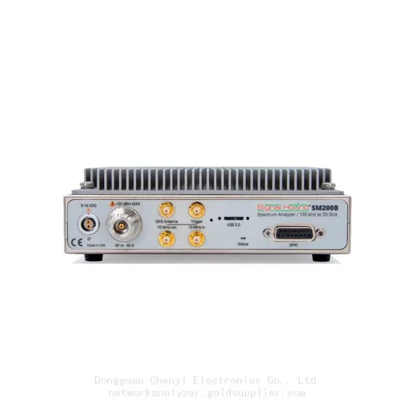
9.3 SM200B / SM200C
Parameter | SM200B | SM200C |
Frequency Range | 100 kHz – 20 GHz | 100 kHz – 20 GHz |
Dynamic Range (typical) | 105 dB | 110 dB |
Real-Time Bandwidth | 40 MHz | 160 MHz |
DANL (typical, 1 GHz, 10 kHz RBW) | -155 dBm | -160 dBm |
Max Input Level | +20 dBm (without damage) | +20 dBm (without damage) |
Power Supply | External 12V DC (1.5A) | External 12V DC (1.5A) |
Dimensions (W x H x D) | 216 x 89 x 279 mm (8.5 x 3.5 x 11.0 in) | 216 x 89 x 279 mm (8.5 x 3.5 x 11.0 in) |
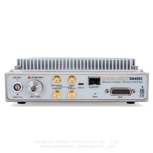
9.4 SM435B / SM435C
Parameter | SM435B | SM435C |
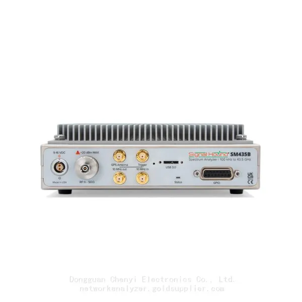
Frequency Range | 100 kHz – 43.5 GHz | 100 kHz – 43.5 GHz |
Dynamic Range (typical) | 105 dB | 110 dB |
Real-Time Bandwidth | 40 MHz | 160 MHz |
DANL (typical, 28 GHz, 10 kHz RBW) | -145 dBm | -150 dBm |
Max Input Level | +28 dBm (without damage) | +28 dBm (without damage) |
Power Supply | External 12V DC (3A) | External 12V DC (3A) |
Dimensions (W x H x D) | 216 x 89 x 356 mm (8.5 x 3.5 x 14.0 in) | 216 x 89 x 356 mm (8.5 x 3.5 x 14.0 in) |
10. Warranty Information
Signal Hound warrants that all spectrum analyzers are free from defects in materials and workmanship for a period of 2 years from the date of purchase. This warranty covers repair or replacement of defective components, provided the device is used in accordance with this manual and has not been modified, misused, or damaged due to negligence or accident.
The following are not covered by the warranty:
• Damage caused by misuse, abuse, or failure to follow safety precautions.
• Damage from electrostatic discharge (ESD) due to improper handling.
• Damage from natural disasters (fire, flood, earthquake, etc.).
• Unauthorized disassembly or repair.
• Consumable parts (cables, adapters) beyond 90 days from purchase.
To make a warranty claim, contact Signal Hound technical support with your purchase receipt, analyzer serial number, and details of the defect. Signal Hound will arrange for repair or replacement of the device, and return it to you at no cost (shipping within the contiguous U.S. only; international shipping costs may apply).
Glossary
• DANL (Displayed Average Noise Level): The lowest signal level a spectrum analyzer can detect, determined by internal noise.
• Dynamic Range: The ratio between the strongest and weakest signals an analyzer can simultaneously detect.
• RBW (Resolution Bandwidth): The bandwidth of the analyzer’s internal filter, determining the ability to distinguish between closely spaced signals.
• Real-Time Bandwidth: The maximum bandwidth of a signal that can be captured and processed in real time.
• TOI (Third-Order Intercept Point): A measure of analyzer linearity, indicating the ability to avoid signal distortion from strong signals.
• ESD (Electrostatic Discharge): A sudden flow of electricity between two objects with different electrical potentials, which can damage sensitive electronic components.
• EMC (Electromagnetic Compatibility): The ability of a device to operate without interfering with other devices or being affected by other devices.
Recently Posted
-
Cost-Benefit Analysis: Why Choose Signal Hound BB60D for RF Testing Projects
July 2, 2026Cost-Benefit Analysis: Why Choose Signal Hound BB60D for RF Testing ProjectsIn enterprise RF testing projects, laboratory scientif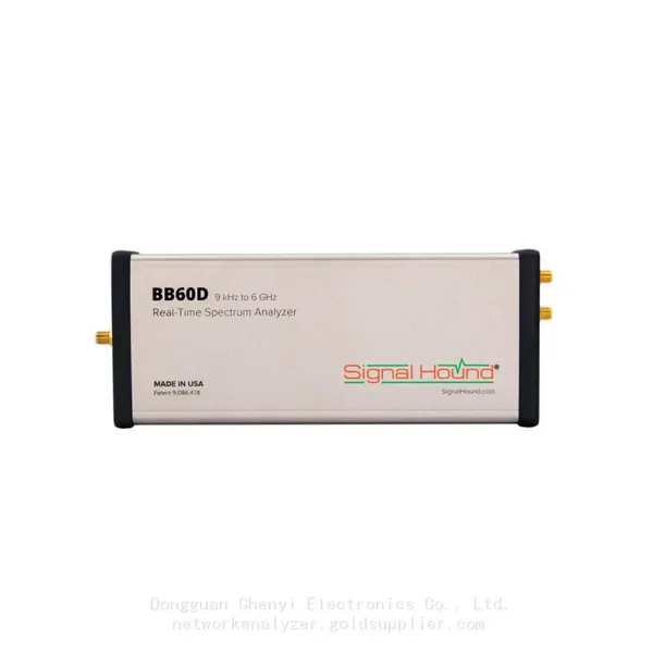 Read More
 -
Ultimate Buying Guide for Signal Hound BB60D Real-Time Spectrum Analyzer: Features, Uses & Benefits
July 2, 2026Ultimate Buying Guide for Signal Hound BB60D Real-Time Spectrum Analyzer: Features, Uses & BenefitsFor RF engineers, laborator Read More
 -
Common Application Scenarios & User Cases of Signal Hound BB60D Spectrum Analyzer
July 2, 2026Common Application Scenarios & User Cases of Signal Hound BB60D Spectrum AnalyzerThe Signal Hound BB60D real-time spectrum ana Read More
 -
Signal Hound BB60D for Radar Signal Analysis & Pulse Signal Testing
July 2, 2026Signal Hound BB60D for Radar Signal Analysis & Pulse Signal TestingRadar signal analysis and pulse signal testing are high-pre
Read More

Contact Us
Recommended Products
-
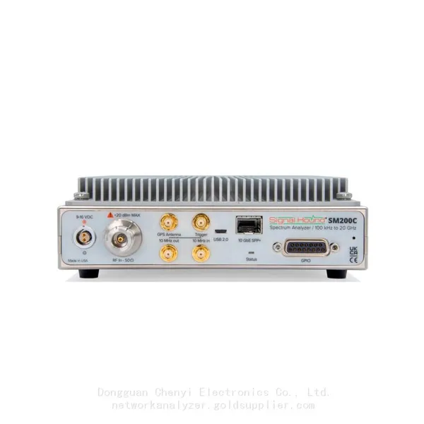
 Signal Hound SM200C 100 KHz to 20 GHz Real-time Spectrum Analyzer With 10GbE Monitoring ReceiversNegotiableMOQ: 1 Unit
 -
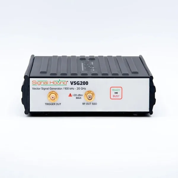
Signal Hound VSG200 Vector Signal Generator 100 KHz to 20 GHzNegotiableMOQ: 1 Unit
-
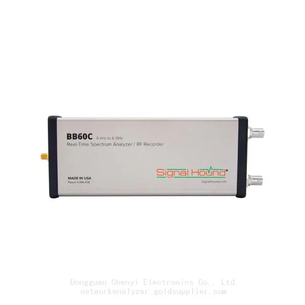
Signal Hound BB60C 9 KHz to 6 GHz Real-time Spectrum AnalyzerNegotiableMOQ: 1 Unit
-
Signal Hound BB60D 9 KHz to 6 GHz Real-time Spectrum AnalyzerNegotiableMOQ: 1 Unit
-
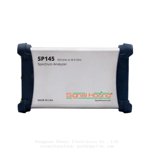
Signal Hound SP145 100 KHz to 14.5 GHz Real-time Spectrum Analyzer Monitoring ReceiversNegotiableMOQ: 1 Unit
-
Signal Hound VSG60A 50 MHz to 6 GHz GHz Vector Signal GeneratorNegotiableMOQ: 1 Unit
-
Signal Hound VSG25A 100 MHz to 2.5 GHz Vector Signal GeneratorNegotiableMOQ: 1 Unit
-
Signal Hound VNA400 40 MHz to 40 GHz 2-port Vector Network AnalyzerNegotiableMOQ: 1 Unit
-
Signal Hound PCR4200 100 KHz to 20 GHz Four-Channel Phase Coherent ReceiverNegotiableMOQ: 1 Unit
-
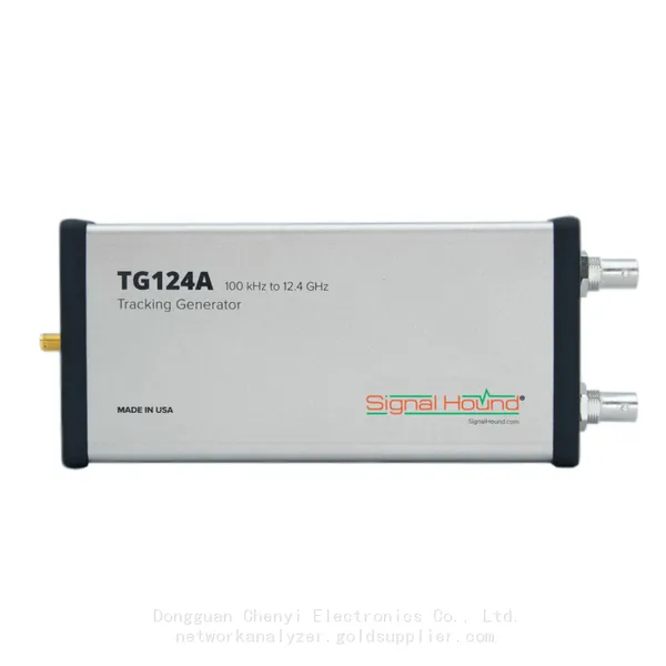
Signal Hound TG124A 100 KHz to 12.4 GHz Tracking GeneratorNegotiableMOQ: 1 Unit
-
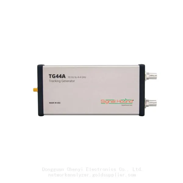
Signal Hound TG44A 10 Hz to 4.4 GHz t Tracking GeneratorNegotiableMOQ: 1 Unit
-
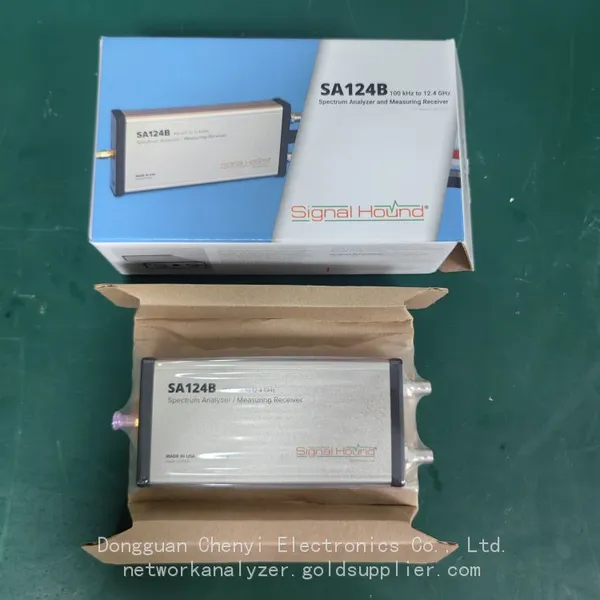
Signal Hound SA124B 100 KHz to 12.4 GHz Spectrum AnalyzerNegotiableMOQ: 1 Unit
-
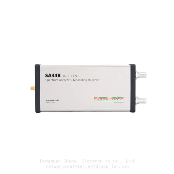
Signal Hound SA44B 1 Hz to 4.4 GHz Spectrum AnalyzerNegotiableMOQ: 1 Unit
-
Signal Hound SM200B 100 KHz to 20 GHz Real-time Spectrum Analyzer Monitoring ReceiversNegotiableMOQ: 1 Unit
-
Signal Hound SM435C 100 KHz to 43.5GHz Real-time Spectrum Analyzer With 10GbE Monitoring ReceiversNegotiableMOQ: 1 Unit
-
Signal Hound SM435B 100 KHz to 43.5GHz Real-time Spectrum Analyzer Monitoring ReceiversNegotiableMOQ: 1 Unit
-
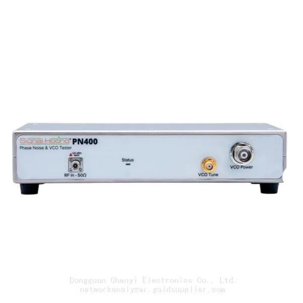
Signal Hound PN400 Phase Noise and VCO Test System 100 KHz to 43.5 GHzNegotiableMOQ: 1 Unit
-
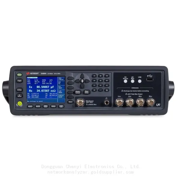
Keysight E4980A Precision LCR Meter 20 Hz to 2 MHzNegotiableMOQ: 1 Unit
-
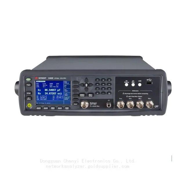
Keysight E4980B and E4980BL Precision LCR Meter 20 Hz to 2 MHzNegotiableMOQ: 1 Unit
-
Keysight U1733C Handheld LCR Meter 100Hz 120Hz 1kHz 10kHz 100kHzNegotiableMOQ: 1 Unit