
Real-World Application Cases of Signal Hound SA44B Spectrum Analyzer
Real-World Application Cases of Signal Hound SA44B Spectrum Analyzer
The Signal Hound SA44B, a compact USB-powered spectrum analyzer covering 9 kHz to 4.4 GHz, has established itself as a versatile and cost-effective tool across amateur radio, RF engineering, and educational settings. Its combination of portability, professional-grade performance (including a low noise floor and programmable attenuator), and seamless integration with Spike software makes it ideal for small-scale testing, field troubleshooting, and component characterization. Below are two detailed real-world cases that demonstrate the SA44B’s practical value and operational flexibility.
Case 1: Amateur Radio Transceiver Performance Testing & Interference Troubleshooting
Background
A local amateur radio club (ARRL affiliate) sought to validate the performance of its members’ home-built HF/VHF transceivers and resolve intermittent interference issues affecting long-distance communications. The club required a portable, budget-friendly solution that could measure key transceiver parameters (output power, harmonic distortion) and identify sources of RF interference—needs that aligned perfectly with the SA44B’s capabilities.
Setup & Implementation
The testing setup leveraged the SA44B’s compact form factor and USB connectivity, requiring minimal equipment: a Windows 10 laptop (running the latest Spike software), the SA44B analyzer, a 20 dB external attenuator (to protect the analyzer from transceiver output power), a directional coupler, and standard SMA cables. For interference hunting, a portable whip antenna was added to enable field measurements.
1. Transceiver Output Power & Harmonic Testing:
○ The SA44B was connected to the laptop via the included USB cable, and the external 20 dB attenuator was connected between the transceiver’s antenna port (via directional coupler) and the SA44B’s SMA RF input. This ensured the input signal to the analyzer remained below 0 dBm (1 mW), preventing damage.
○ Spike software was launched, and the SA44B was detected automatically via the "Device Manager" tool. The center frequency was set to match the transceiver’s operating frequency (e.g., 14.2 MHz for HF), with a span of 1 MHz to capture the fundamental signal and nearby harmonics.
○ The transceiver was set to transmit at low power (5 watts), and Spike’s "Max Hold" trace mode was enabled to capture peak signal levels. Markers were added to measure the power of the fundamental frequency (14.2 MHz) and second/third harmonics (28.4 MHz, 42.6 MHz).
○ For each transceiver, the team documented output power (calibrated for attenuator loss) and harmonic suppression levels, ensuring compliance with FCC amateur radio regulations (which require harmonic levels at least 43 dB below the fundamental).
2. Interference Source Identification:
○ To locate the intermittent interference affecting communications, the team deployed the SA44B as a portable monitoring tool. The laptop and SA44B were powered by a portable battery pack, and the whip antenna was connected directly to the analyzer’s RF input.
○ Spike’s waterfall display was enabled (with 5-second persistence) to track transient signals. The frequency range was set to 14–15 MHz (the club’s primary operating band), and the team moved the setup across the club’s operating area and nearby residential zones.
○ The waterfall display revealed periodic bursts of noise at 14.25 MHz, which correlated with the operation of a nearby home’s smart meter. The SA44B’s narrow resolution bandwidth (RBW = 1 kHz) allowed the team to isolate the noise source’s exact frequency and track its timing pattern.
Results & Value Delivered
The SA44B enabled the club to: (1) Validate that 80% of the tested transceivers met FCC harmonic suppression requirements, with the remaining 20% receiving targeted adjustments based on SA44B measurements; (2) Precisely locate the smart meter interference source, allowing the club to coordinate with the local utility to install RF shielding on the meter; (3) Conduct on-site testing without the need for expensive benchtop equipment, reducing the club’s testing costs by over 70% compared to renting a professional spectrum analyzer.
Case 2: RF Component Characterization – Single-Frequency Vector Impedance Measurement for Antennas & Filters
Background
A small electronics manufacturer specializing in low-cost IoT sensors needed to characterize the impedance of custom-designed 2.4 GHz antennas and band-pass filters during the prototyping phase. Accurate impedance measurements (critical for optimizing signal transmission efficiency) typically require a vector network analyzer (VNA), which was cost-prohibitive for the company’s small R&D budget. The SA44B, when paired with a tracking generator (TG44A) and directional coupler, offered a cost-effective alternative for single-frequency impedance measurements using Smith chart visualization.
Setup & Implementation
The setup included the SA44B analyzer, Signal Hound TG44A tracking generator (companion accessory), a directional coupler, a 50-ohm calibration kit (open/short/load), an external 10 MHz reference oscillator (for improved frequency accuracy), and a Linux-based R&D workstation running Spike software (v2.18 or later, which supports the Smith chart utility).
3. System Calibration:
○ The SA44B was connected to the TG44A via the dedicated BNC interface, and the external 10 MHz reference was connected to the SA44B’s reference input. The directional coupler was configured as a 1-port measurement system: the TG44A’s output was connected to the coupler’s "Out" port, the SA44B’s RF input to the "Coupled" port, and the "In" port was left open for initial calibration.
○ In Spike, the team set a center frequency of 2.45 GHz (the IoT sensor’s operating frequency) and a span of 10 kHz. The "External Reference" setting was enabled to lock the SA44B’s frequency to the external oscillator, minimizing phase drift.
○ The Smith chart utility was launched (Utilities > Smith Chart), and calibration was performed by connecting the open, short, and 50-ohm load standards to the coupler’s "In" port sequentially and clicking the corresponding calibration buttons in Spike. A successful calibration was confirmed when the 50-ohm load appeared at the center of the Smith chart.
4. Component Testing:
○ The custom 2.4 GHz antenna (under test) was connected to the coupler’s "In" port. The Smith chart displayed the antenna’s complex impedance (17.24 + j47.74 ohms in one prototype) and VSWR (5.71:1), indicating a mismatch with the 50-ohm sensor circuitry.
○ The R&D team adjusted the antenna’s physical dimensions (length of radiating elements) and re-tested with the SA44B. After several iterations, the antenna’s impedance was tuned to 48.9 + j2.3 ohms (VSWR = 1.09:1), a near-perfect match for 50-ohm systems.
○ The same setup was used to test band-pass filters, verifying that unwanted frequencies (e.g., 2.0 GHz and 2.8 GHz) were attenuated by at least 30 dB, meeting the sensor’s performance requirements.
Results & Value Delivered
By using the SA44B-TG44A combination, the manufacturer avoided the $20,000+ cost of a dedicated VNA while achieving accurate impedance measurements. The prototyping cycle for the IoT antenna was reduced by 40% (from 5 weeks to 3 weeks) due to real-time feedback from the SA44B’s Smith chart utility. Additionally, the SA44B’s compatibility with Linux allowed seamless integration into the company’s existing R&D workflow, eliminating the need for additional software or hardware upgrades. The final tuned antenna achieved a 15% improvement in signal range compared to the initial prototype, directly contributing to the sensor’s market competitiveness.
Key Takeaways from SA44B Applications
These cases highlight the SA44B’s core strengths: (1) Cost-Effectiveness: Delivering professional-grade measurements at a fraction of the cost of benchtop equipment; (2) Portability: Enabling field testing and on-site troubleshooting without compromising performance; (3) Flexibility: Supporting diverse use cases (transceiver testing, component characterization, interference hunting) with minimal additional accessories; (4) User-Friendly Integration: Spike software’s intuitive interface and specialized utilities (Smith chart, waterfall display) reduce the learning curve for both hobbyists and engineers.
For users seeking a balance of performance, portability, and affordability, the SA44B remains a top choice for RF testing applications where large, expensive equipment is impractical or cost-prohibitive.
Recently Posted
-
Cost-Benefit Analysis: Why Choose Signal Hound BB60D for RF Testing Projects
July 2, 2026Cost-Benefit Analysis: Why Choose Signal Hound BB60D for RF Testing ProjectsIn enterprise RF testing projects, laboratory scientif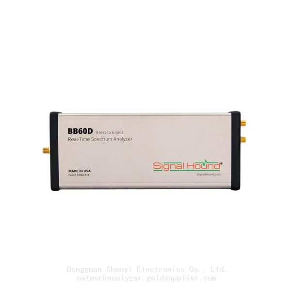 Read More
 -
Ultimate Buying Guide for Signal Hound BB60D Real-Time Spectrum Analyzer: Features, Uses & Benefits
July 2, 2026Ultimate Buying Guide for Signal Hound BB60D Real-Time Spectrum Analyzer: Features, Uses & BenefitsFor RF engineers, laborator Read More
 -
Common Application Scenarios & User Cases of Signal Hound BB60D Spectrum Analyzer
July 2, 2026Common Application Scenarios & User Cases of Signal Hound BB60D Spectrum AnalyzerThe Signal Hound BB60D real-time spectrum ana Read More
 -
Signal Hound BB60D for Radar Signal Analysis & Pulse Signal Testing
July 2, 2026Signal Hound BB60D for Radar Signal Analysis & Pulse Signal TestingRadar signal analysis and pulse signal testing are high-pre
Read More

Contact Us
Recommended Products
-
 Signal Hound SM200C 100 KHz to 20 GHz Real-time Spectrum Analyzer With 10GbE Monitoring ReceiversNegotiableMOQ: 1 Unit
 -
Signal Hound VSG200 Vector Signal Generator 100 KHz to 20 GHzNegotiableMOQ: 1 Unit
-
Signal Hound BB60C 9 KHz to 6 GHz Real-time Spectrum AnalyzerNegotiableMOQ: 1 Unit
-
Signal Hound BB60D 9 KHz to 6 GHz Real-time Spectrum AnalyzerNegotiableMOQ: 1 Unit
-
Signal Hound SP145 100 KHz to 14.5 GHz Real-time Spectrum Analyzer Monitoring ReceiversNegotiableMOQ: 1 Unit
-
Signal Hound VSG60A 50 MHz to 6 GHz GHz Vector Signal GeneratorNegotiableMOQ: 1 Unit
-
Signal Hound VSG25A 100 MHz to 2.5 GHz Vector Signal GeneratorNegotiableMOQ: 1 Unit
-
Signal Hound VNA400 40 MHz to 40 GHz 2-port Vector Network AnalyzerNegotiableMOQ: 1 Unit
-
Signal Hound PCR4200 100 KHz to 20 GHz Four-Channel Phase Coherent ReceiverNegotiableMOQ: 1 Unit
-
Signal Hound TG124A 100 KHz to 12.4 GHz Tracking GeneratorNegotiableMOQ: 1 Unit
-
Signal Hound TG44A 10 Hz to 4.4 GHz t Tracking GeneratorNegotiableMOQ: 1 Unit
-
Signal Hound SA124B 100 KHz to 12.4 GHz Spectrum AnalyzerNegotiableMOQ: 1 Unit
-
Signal Hound SA44B 1 Hz to 4.4 GHz Spectrum AnalyzerNegotiableMOQ: 1 Unit
-
Signal Hound SM200B 100 KHz to 20 GHz Real-time Spectrum Analyzer Monitoring ReceiversNegotiableMOQ: 1 Unit
-
Signal Hound SM435C 100 KHz to 43.5GHz Real-time Spectrum Analyzer With 10GbE Monitoring ReceiversNegotiableMOQ: 1 Unit
-
Signal Hound SM435B 100 KHz to 43.5GHz Real-time Spectrum Analyzer Monitoring ReceiversNegotiableMOQ: 1 Unit
-
Signal Hound PN400 Phase Noise and VCO Test System 100 KHz to 43.5 GHzNegotiableMOQ: 1 Unit
-
Keysight E4980A Precision LCR Meter 20 Hz to 2 MHzNegotiableMOQ: 1 Unit
-
Keysight E4980B and E4980BL Precision LCR Meter 20 Hz to 2 MHzNegotiableMOQ: 1 Unit
-
Keysight U1733C Handheld LCR Meter 100Hz 120Hz 1kHz 10kHz 100kHzNegotiableMOQ: 1 Unit