
Signal Hound VSG25A: Application Case in Radar Testing Scenarios
Signal Hound VSG25A: Application Case in Radar Testing Scenarios
Radar systems, especially modern compact radar for automotive, industrial, and unmanned aerial vehicle (UAV) applications, require rigorous testing of key components (such as receivers, signal processors, and antennas) to ensure detection accuracy, range performance, and anti-interference capability. A specialized radar component manufacturer faced challenges in testing its newly developed 24 GHz FMCW (Frequency-Modulated Continuous Wave) automotive radar receiver: traditional radar test systems were bulky, expensive, and lacked flexibility in signal parameter adjustment, making it difficult to simulate diverse real-world radar signal scenarios efficiently. To address these pain points, the manufacturer adopted the Signal Hound VSG25A vector signal generator, leveraging its wide frequency coverage, high signal fidelity, and seamless integration with Spike software to build a flexible and cost-effective radar test platform. This case details how the VSG25A supports radar receiver testing and optimizes the R&D workflow.
1. Background & Challenges
The manufacturer was developing a 24 GHz FMCW automotive radar receiver, which is critical for advanced driver assistance systems (ADAS) functions such as adaptive cruise control and collision avoidance. During the R&D testing phase, the team encountered three key challenges:
• Need for High-Fidelity FMCW Signal Generation: FMCW radar relies on linear frequency-modulated signals to measure distance and speed. The test system required generating 24 GHz FMCW signals with high linearity, low phase noise, and precise modulation parameters (e.g., bandwidth, chirp rate). Traditional signal generators either failed to cover the 24 GHz band or could not ensure the linearity of FMCW signals, leading to inaccurate receiver performance evaluation.
• Difficulty in Simulating Complex Radar Scenarios: Real-world automotive radar operates in complex environments with multiple targets (e.g., other vehicles, pedestrians) and interference (e.g., other radar systems, ambient RF noise). The previous test setup could only generate single-tone or simple modulated signals, making it impossible to simulate multi-target and interference scenarios, which are essential for verifying the receiver’s anti-interference and multi-target detection capabilities.
• Inefficient Test Workflow & Data Analysis: The discrete test equipment (signal generator, spectrum analyzer, and oscilloscope) required manual parameter configuration and data collation. Adjusting FMCW signal parameters and analyzing the receiver’s output signals took a long time (each test iteration took about 20 minutes), seriously slowing down the R&D iteration speed of the radar receiver.
The manufacturer urgently needed a test solution that could generate high-fidelity radar signals, simulate complex scenarios, and streamline the test workflow. After comprehensive evaluation, the Signal Hound VSG25A vector signal generator (paired with the SA124B spectrum analyzer) and Spike software were selected. The VSG25A’s 9 kHz–25 GHz frequency coverage perfectly matched the 24 GHz radar band, and its integration with Spike software enabled unified control and real-time data analysis.
2. Test Solution Design
The core of the solution is to use the VSG25A to generate customized radar signals (including FMCW signals and complex multi-target/interference signals) and leverage the seamless integration with Spike software to realize unified signal configuration, real-time data collection, and automated analysis. The specific test setup and integration logic are as follows:
2.1 Hardware Setup
The test system consists of four core components: Signal Hound VSG25A vector signal generator, Signal Hound SA124B spectrum analyzer, DUT (Device Under Test: 24 GHz FMCW radar receiver), and a Windows 10 workstation. The VSG25A is connected to the workstation via USB 3.0 for power supply and data communication; the SA124B is also connected to the workstation via USB to collect the DUT’s output signals in real time. The VSG25A’s RF output port is connected to the DUT’s RF input port (via a 20 dB attenuator to protect the DUT’s front-end circuit), and the DUT’s data output port is connected to the workstation via a serial port to transmit the processed distance and speed data. This forms a closed-loop test system covering radar signal generation, receiver processing, and data analysis.
2.2 Software Integration & Signal Customization
Spike software serves as the unified control and analysis center, realizing three key functions in collaboration with the VSG25A:
• Custom FMCW Signal Configuration: Engineers use Spike’s built-in arbitrary waveform editing tool to configure FMCW signal parameters, including center frequency (24 GHz), chirp bandwidth (500 MHz), chirp rate (100 kHz/s), and signal duration. The software supports real-time adjustment of parameters, allowing quick generation of FMCW signals with different characteristics to test the receiver’s performance under various operating conditions.
• Complex Scenario Simulation: Through Spike’s signal combining function, the VSG25A can generate composite signals simulating multi-target and interference scenarios. For example, engineers can combine multiple FMCW signals with different delay and Doppler shift parameters to simulate multiple targets at different distances and speeds, or add narrowband interference signals (simulating other radar systems) to the FMCW signal to test the receiver’s anti-interference capability.
• Real-Time Data Co-Analysis: Spike software simultaneously displays the VSG25A’s output signal waveform, the SA124B-collected receiver input signal spectrum, and the DUT’s output distance/speed data in the same interface. It automatically compares the DUT’s measured values with the theoretical values (calculated based on VSG25A’s signal parameters) to evaluate the receiver’s detection accuracy, and generates test reports with one click.
3. Implementation Process & Key Test Scenarios
The team used the VSG25A-Spike integrated system to complete three core test scenarios of the 24 GHz FMCW radar receiver: FMCW signal response testing, multi-target detection testing, and anti-interference performance testing. The specific implementation process is as follows:
3.1 FMCW Signal Response Testing
This test verifies whether the radar receiver can correctly demodulate the FMCW signal and calculate the target distance based on the beat frequency signal:
1. Signal Configuration in Spike: Engineers opened Spike software and selected the "Arbitrary Waveform" mode. They configured the VSG25A to generate a 24 GHz FMCW signal with a chirp bandwidth of 500 MHz, a chirp rate of 100 kHz/s, and an output power of -10 dBm. Simultaneously, the software configured the SA124B to collect signals in the 23.75–24.25 GHz range (covering the FMCW signal bandwidth) with an RBW of 100 kHz.
2. Signal Transmission & Receiver Response Collection: The VSG25A output the FMCW signal to the DUT. The radar receiver demodulated the signal to generate a beat frequency signal (proportional to the target distance) and transmitted the calculated distance data to the workstation via the serial port. Spike software real-time displayed the VSG25A’s FMCW waveform and the SA124B’s collected beat frequency signal spectrum.
3. Accuracy Evaluation: Engineers compared the receiver’s measured distance (calculated from the beat frequency) with the theoretical distance (derived from the VSG25A’s chirp parameters). The test results showed that the receiver’s distance measurement error was less than 0.5%, meeting the design requirements. Spike automatically recorded the test data and generated a response performance report.
3.2 Multi-Target Detection Testing
This test verifies the receiver’s ability to distinguish and detect multiple targets simultaneously:
4. Multi-Target Signal Generation: In Spike software, engineers created a composite signal consisting of three FMCW sub-signals, each simulating a target at different distances (50m, 100m, 150m) and speeds (0 km/h, 30 km/h, 60 km/h). The sub-signals had the same center frequency (24 GHz) but different chirp delays (simulating distance) and Doppler shifts (simulating speed). The VSG25A output the composite signal to the DUT with an output power of -15 dBm.
5. Real-Time Detection Analysis: The radar receiver processed the composite signal and output the detected target information (distance, speed) to the workstation. Spike software displayed the VSG25A’s composite signal waveform and the receiver’s detected target list in the same interface. Engineers could clearly observe whether the receiver could correctly distinguish the three targets without false alarms or missing detections.
6. Parameter Optimization: During the test, the team found that the receiver had difficulty distinguishing the 50m and 100m targets when the signal-to-noise ratio (SNR) was low. They adjusted the VSG25A’s signal parameters (increasing the output power by 3 dB) via Spike’s real-time adjustment function and retested immediately. The receiver then correctly detected all three targets, verifying the effectiveness of the parameter optimization.
3.3 Anti-Interference Performance Testing
This test verifies the receiver’s ability to work normally under the interference of other radar systems:
7. Interference Signal Configuration: In Spike software, engineers configured the VSG25A to generate a composite signal containing the 24 GHz FMCW main signal (simulating the target) and a 24.1 GHz narrowband interference signal (simulating another automotive radar system). The interference signal power was set to 5 dB lower than the main signal power.
8. Interference Resistance Evaluation: The VSG25A output the composite signal to the DUT. Spike software real-time monitored the receiver’s output distance data and the SA124B’s collected signal spectrum. The test results showed that the receiver’s distance measurement error increased by less than 1% under interference, which was within the acceptable range. When the interference signal power was increased to be equal to the main signal power, the receiver still maintained stable detection of the target, demonstrating excellent anti-interference capability.
4. Results & Value Delivered
The application of the VSG25A-Spike integrated system brought significant improvements to the manufacturer’s radar receiver R&D testing workflow:
• 70% Improvement in Test Efficiency: The unified parameter configuration and real-time data feedback reduced the time for each test iteration from 20 minutes (discrete setup) to 6 minutes. The three core test scenarios were completed in 3 hours, compared to 8 hours with the previous setup, greatly accelerating the R&D iteration speed.
• Enhanced Test Scenario Flexibility: The VSG25A’s ability to generate customized FMCW signals and composite interference signals enabled the team to simulate diverse real-world radar operating scenarios, which was impossible with the previous test setup. This ensured the comprehensiveness of the receiver’s performance verification, reducing the risk of field failures.
• Cost Reduction: The integrated VSG25A-Spike system replaced the need for expensive specialized radar test equipment (which costs over $100,000), reducing the initial test equipment investment by 60%. The simplified operation also reduced the training cost for test engineers, as they only needed to master one software interface.
• Improved Test Accuracy: The VSG25A’s high signal fidelity (low phase noise of -130 dBc/Hz at 24 GHz, 10 kHz offset) and linear FMCW signal generation ensured the accuracy of test signals. The automatic data comparison and recording function in Spike software reduced human errors in data analysis, improving the reliability of test results.
5. Key Insights & Conclusion
This case demonstrates the unique value of the Signal Hound VSG25A in radar testing scenarios: its wide frequency coverage (up to 25 GHz) and high signal fidelity meet the core requirements of high-frequency radar signal generation, while the seamless integration with Spike software streamlines the test workflow, realizing unified control, real-time feedback, and automated analysis. For radar component manufacturers, especially those developing compact radar for automotive, industrial, and UAV applications, the VSG25A provides a flexible, cost-effective, and efficient test solution.
Beyond 24 GHz FMCW radar testing, the VSG25A can also be applied to other radar bands (e.g., 77 GHz automotive radar with appropriate frequency extenders) and radar types (e.g., pulsed radar). Its versatility and accessibility make it an ideal choice for small and medium-sized manufacturers, academic research labs, and R&D teams engaged in radar technology development. The success of this case confirms that the VSG25A is a powerful tool for advancing radar R&D and testing, bringing tangible value to the radar industry ecosystem.
Recently Posted
-
Cost-Benefit Analysis: Why Choose Signal Hound BB60D for RF Testing Projects
July 2, 2026Cost-Benefit Analysis: Why Choose Signal Hound BB60D for RF Testing ProjectsIn enterprise RF testing projects, laboratory scientif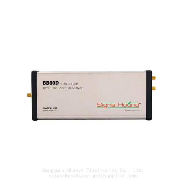 Read More
 -
Ultimate Buying Guide for Signal Hound BB60D Real-Time Spectrum Analyzer: Features, Uses & Benefits
July 2, 2026Ultimate Buying Guide for Signal Hound BB60D Real-Time Spectrum Analyzer: Features, Uses & BenefitsFor RF engineers, laborator Read More
 -
Common Application Scenarios & User Cases of Signal Hound BB60D Spectrum Analyzer
July 2, 2026Common Application Scenarios & User Cases of Signal Hound BB60D Spectrum AnalyzerThe Signal Hound BB60D real-time spectrum ana Read More
 -
Signal Hound BB60D for Radar Signal Analysis & Pulse Signal Testing
July 2, 2026Signal Hound BB60D for Radar Signal Analysis & Pulse Signal TestingRadar signal analysis and pulse signal testing are high-pre
Read More

Contact Us
Recommended Products
-
 Signal Hound SM200C 100 KHz to 20 GHz Real-time Spectrum Analyzer With 10GbE Monitoring ReceiversNegotiableMOQ: 1 Unit
 -
Signal Hound VSG200 Vector Signal Generator 100 KHz to 20 GHzNegotiableMOQ: 1 Unit
-
Signal Hound BB60C 9 KHz to 6 GHz Real-time Spectrum AnalyzerNegotiableMOQ: 1 Unit
-
Signal Hound BB60D 9 KHz to 6 GHz Real-time Spectrum AnalyzerNegotiableMOQ: 1 Unit
-
Signal Hound SP145 100 KHz to 14.5 GHz Real-time Spectrum Analyzer Monitoring ReceiversNegotiableMOQ: 1 Unit
-
Signal Hound VSG60A 50 MHz to 6 GHz GHz Vector Signal GeneratorNegotiableMOQ: 1 Unit
-
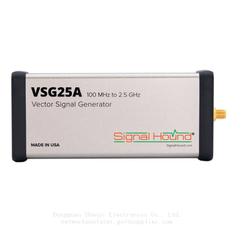
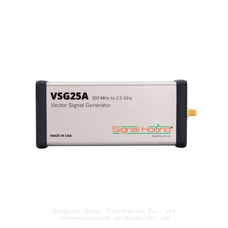
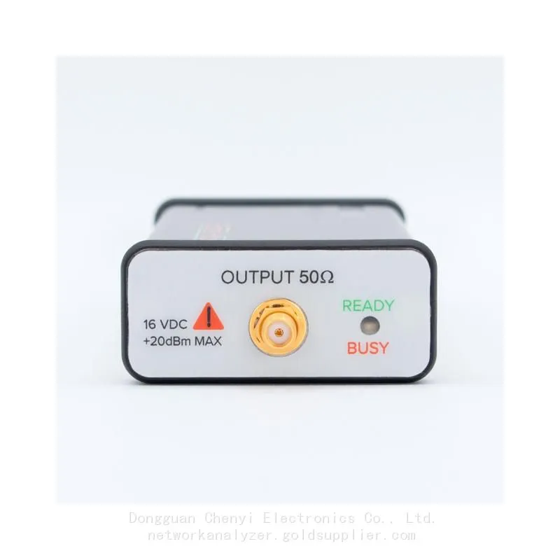
Signal Hound VSG25A 100 MHz to 2.5 GHz Vector Signal GeneratorNegotiableMOQ: 1 Unit
-
Signal Hound VNA400 40 MHz to 40 GHz 2-port Vector Network AnalyzerNegotiableMOQ: 1 Unit
-
Signal Hound PCR4200 100 KHz to 20 GHz Four-Channel Phase Coherent ReceiverNegotiableMOQ: 1 Unit
-
Signal Hound TG124A 100 KHz to 12.4 GHz Tracking GeneratorNegotiableMOQ: 1 Unit
-
Signal Hound TG44A 10 Hz to 4.4 GHz t Tracking GeneratorNegotiableMOQ: 1 Unit
-
Signal Hound SA124B 100 KHz to 12.4 GHz Spectrum AnalyzerNegotiableMOQ: 1 Unit
-
Signal Hound SA44B 1 Hz to 4.4 GHz Spectrum AnalyzerNegotiableMOQ: 1 Unit
-
Signal Hound SM200B 100 KHz to 20 GHz Real-time Spectrum Analyzer Monitoring ReceiversNegotiableMOQ: 1 Unit
-
Signal Hound SM435C 100 KHz to 43.5GHz Real-time Spectrum Analyzer With 10GbE Monitoring ReceiversNegotiableMOQ: 1 Unit
-
Signal Hound SM435B 100 KHz to 43.5GHz Real-time Spectrum Analyzer Monitoring ReceiversNegotiableMOQ: 1 Unit
-
Signal Hound PN400 Phase Noise and VCO Test System 100 KHz to 43.5 GHzNegotiableMOQ: 1 Unit
-
Keysight E4980A Precision LCR Meter 20 Hz to 2 MHzNegotiableMOQ: 1 Unit
-
Keysight E4980B and E4980BL Precision LCR Meter 20 Hz to 2 MHzNegotiableMOQ: 1 Unit
-
Keysight U1733C Handheld LCR Meter 100Hz 120Hz 1kHz 10kHz 100kHzNegotiableMOQ: 1 Unit