
 Business License

Signal Hound TG124A RF Signal Generator Product Manual
Signal Hound TG124A RF Signal Generator Product Manual
1. Introduction
1.1 Overview
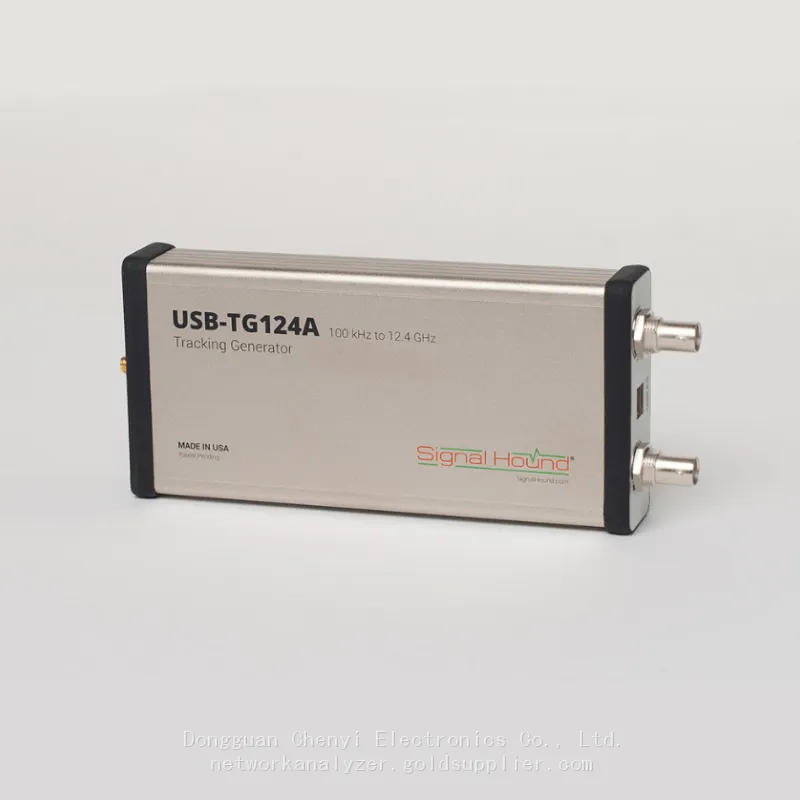
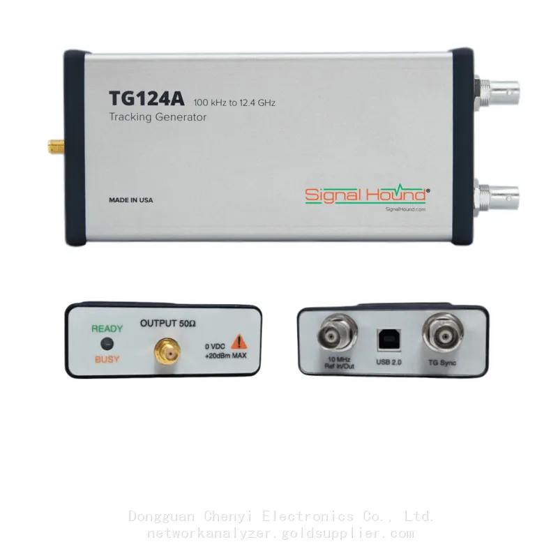
The Signal Hound TG124A is a compact, cost-effective, and USB-powered RF signal generator designed for general-purpose RF testing, component characterization, educational applications, and small-scale research projects. Covering a frequency range of 9 kHz to 2.4 GHz, the TG124A delivers reliable signal generation capabilities for low-to-mid RF band applications, including IoT (Internet of Things) devices, Bluetooth, Zigbee, Wi-Fi (2.4 GHz), and basic RF component testing. Its lightweight design, seamless integration with Spike® RF analysis software, and user-friendly operation make it an ideal solution for both lab environments and field testing scenarios where portability and simplicity are prioritized.
1.2 Scope of This Manual
This manual provides comprehensive guidance on the Signal Hound TG124A, including technical specifications, key features, hardware installation, software setup, basic operation procedures, application scenarios, routine maintenance, and troubleshooting. It is intended for engineers, technicians, researchers, educators, and students who use the TG124A for RF signal generation and related testing tasks.
1.3 Safety Information
• Before operating the TG124A, carefully read all safety instructions and technical specifications to prevent equipment damage or personal injury.
• Operate the device only within the specified environmental conditions (temperature: 0°C to 50°C; humidity: 10% to 90% non-condensing).
• Use only the recommended power sources (USB 3.0/2.0 or optional 5V DC power supply) to avoid electrical damage to the device.
• Avoid exposing the TG124A to extreme temperatures, moisture, dust, direct sunlight, or physical shock.
• Do not disassemble the device without authorization. For repairs or maintenance, contact Signal Hound technical support.
• When connecting RF cables, ensure proper and secure mating to prevent damage to the SMA connectors. Use external attenuators when testing high-power devices to protect the TG124A’s RF front end.
• Disconnect the power supply before connecting or disconnecting RF cables or other peripherals to avoid signal interference or equipment damage.
2. Technical Specifications
Parameter | Specification |
Frequency Range | 9 kHz to 2.4 GHz |
Frequency Accuracy | ±5 ppm (typical) over operating temperature range |
Phase Noise (Typical) | -120 dBc/Hz at 1 GHz, 10 kHz offset |
Output Power Range | -60 dBm to +10 dBm (typical) |
Power Accuracy | ±1 dB (typical) from 100 MHz to 2.4 GHz |
Attenuation | 0–60 dB, step size 0.1 dB |
Modulation Formats | Analog: AM, FM, PM, Pulse; Digital: QPSK, 16QAM; Custom IQ Waveform Playback |
Waveform Memory | Up to 4 GSamples (16-bit resolution) |
Interfaces | USB 3.0 Type-C (power & communication); SMA Female (RF Output); 10 MHz Reference In (SMA Female, optional) |

Recently Posted
-
Software-Defined Instruments: How USB Spectrum Analyzers Are Changing the RF Testing Industry
August 17, 20261. The Benchtop Instrument That Would Not Fit in a Carry-OnAn RF field engineer arrived at a remote cell site in a mountainous reg Read More
 -
Spectrum Monitoring Solutions for Broadcast Radio and Television Transmission Stations
August 17, 20261. When a 50 kW FM Transmitter Goes SilentA regional FM broadcaster serving roughly 2 million listeners lost its main transmitter Read More
 -
Understanding Spectrum Analyzer Key Specifications: DANL, Phase Noise, TOI, and RBW
August 14, 20261. The Specification That Cost Two Weeks of DebuggingAn RF design team spent two weeks trying to measure the third harmonic of a 2 Read More
 -
Real-Time Spectrum Analyzer vs Traditional Swept Spectrum Analyzer: Which One Fits Modern RF Testing
August 13, 20261. The Purchase Decision That Engineers Keep Getting WrongA test equipment manager at a contract manufacturer ordered three tradit Read More

Contact Us
Recommended Products
-
 Signal Hound SM200C 100 KHz to 20 GHz Real-time Spectrum Analyzer With 10GbE Monitoring ReceiversNegotiableMOQ: 1 Unit
 -
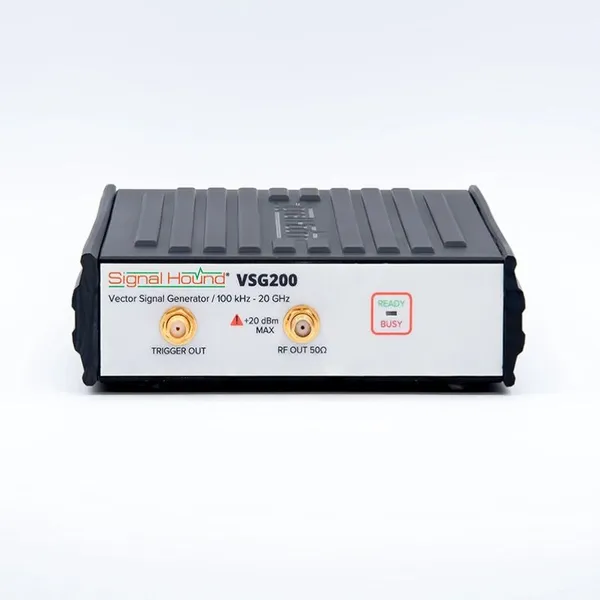
Signal Hound VSG200 Vector Signal Generator 100 KHz to 20 GHzNegotiableMOQ: 1 Unit
-
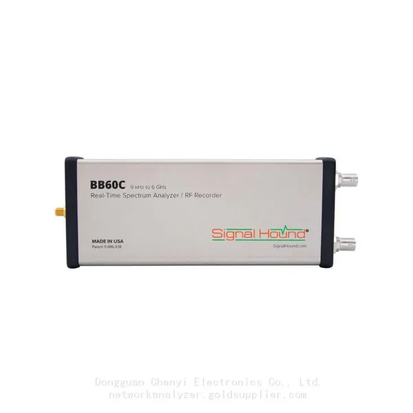
Signal Hound BB60C 9 KHz to 6 GHz Real-time Spectrum AnalyzerNegotiableMOQ: 1 Unit
-
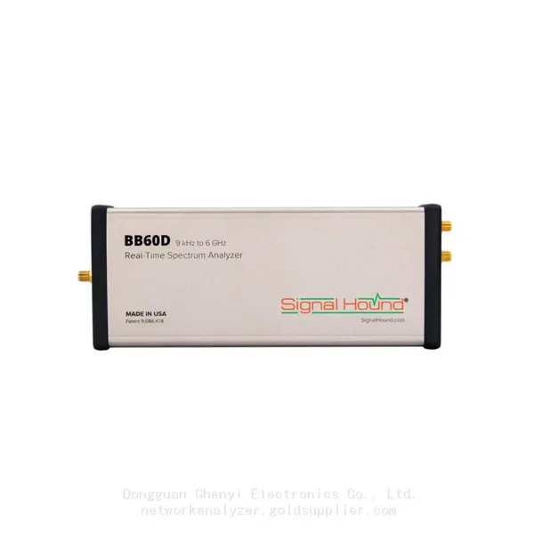
Signal Hound BB60D 9 KHz to 6 GHz Real-time Spectrum AnalyzerNegotiableMOQ: 1 Unit
-
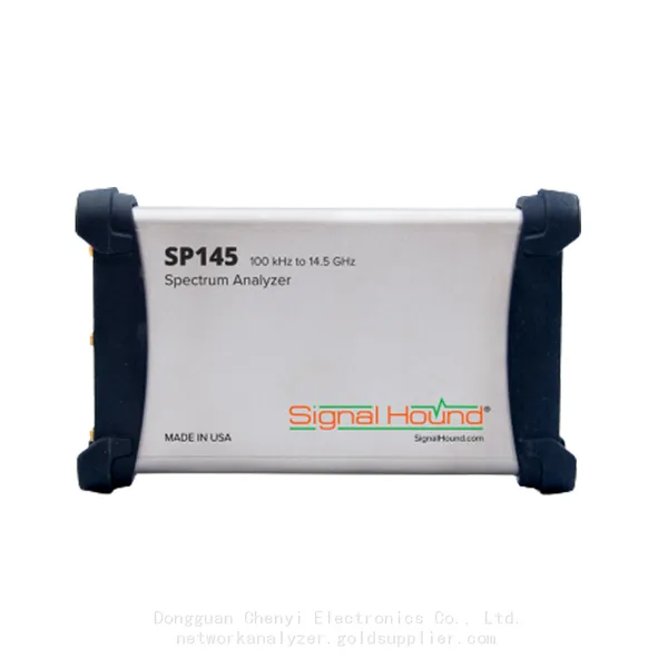
Signal Hound SP145 100 KHz to 14.5 GHz Real-time Spectrum Analyzer Monitoring ReceiversNegotiableMOQ: 1 Unit
-
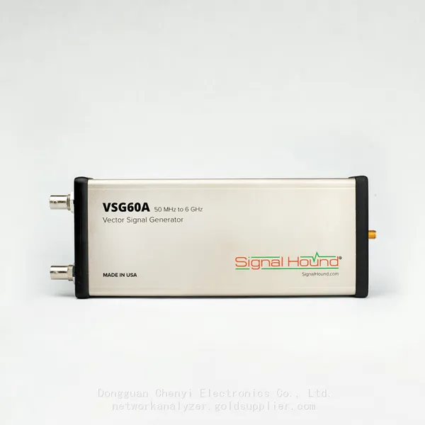
Signal Hound VSG60A 50 MHz to 6 GHz GHz Vector Signal GeneratorNegotiableMOQ: 1 Unit
-
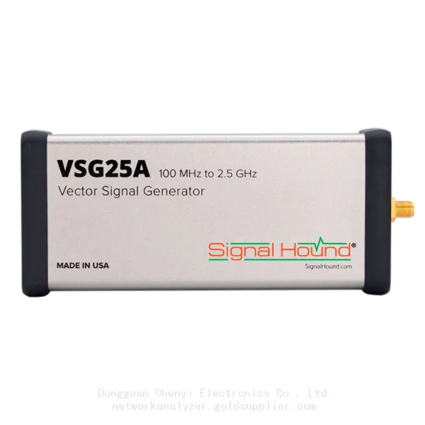
Signal Hound VSG25A 100 MHz to 2.5 GHz Vector Signal GeneratorNegotiableMOQ: 1 Unit
-
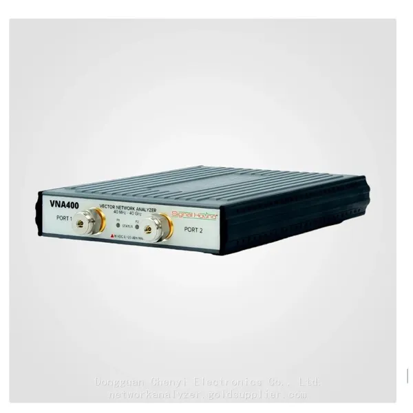
Signal Hound VNA400 40 MHz to 40 GHz 2-port Vector Network AnalyzerNegotiableMOQ: 1 Unit
-
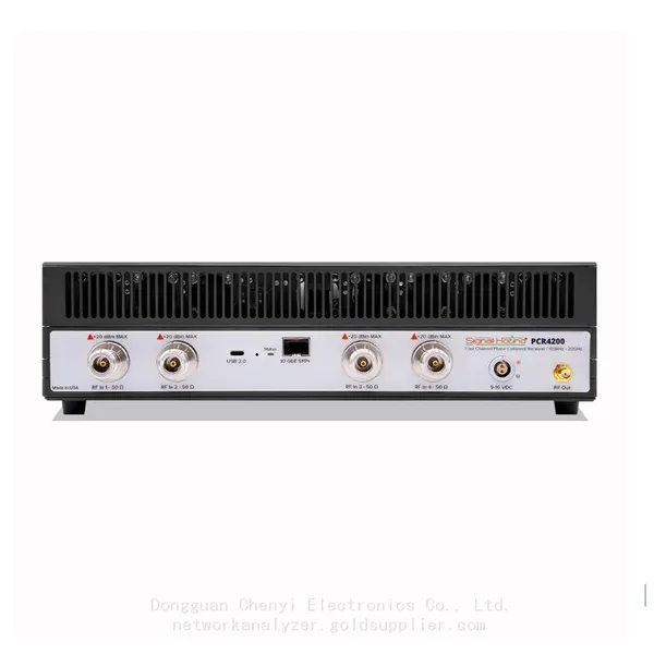
Signal Hound PCR4200 100 KHz to 20 GHz Four-Channel Phase Coherent ReceiverNegotiableMOQ: 1 Unit
-
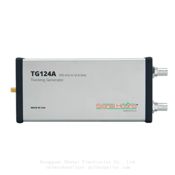
Signal Hound TG124A 100 KHz to 12.4 GHz Tracking GeneratorNegotiableMOQ: 1 Unit
-
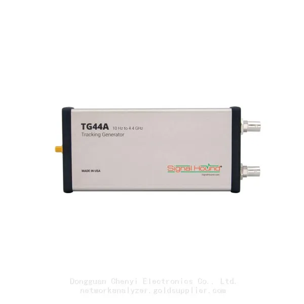
Signal Hound TG44A 10 Hz to 4.4 GHz t Tracking GeneratorNegotiableMOQ: 1 Unit
-
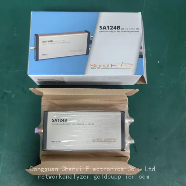
Signal Hound SA124B 100 KHz to 12.4 GHz Spectrum AnalyzerNegotiableMOQ: 1 Unit
-
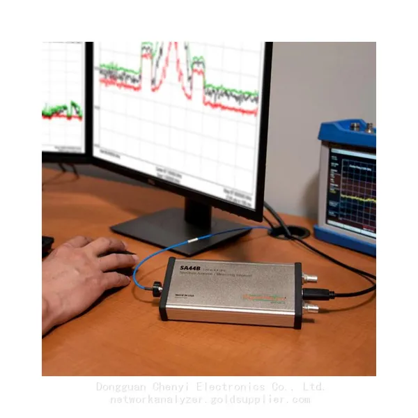
Signal Hound SA44B 1 Hz to 4.4 GHz Spectrum AnalyzerNegotiableMOQ: 1 Unit
-
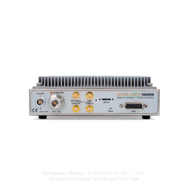
Signal Hound SM200B 100 KHz to 20 GHz Real-time Spectrum Analyzer Monitoring ReceiversNegotiableMOQ: 1 Unit
-
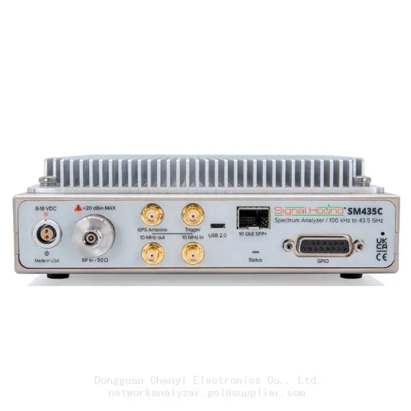
Signal Hound SM435C 100 KHz to 43.5GHz Real-time Spectrum Analyzer With 10GbE Monitoring ReceiversNegotiableMOQ: 1 Unit
-
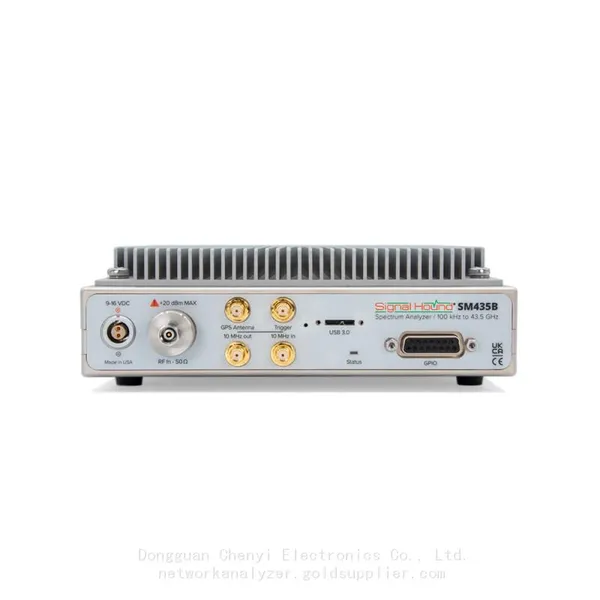
Signal Hound SM435B 100 KHz to 43.5GHz Real-time Spectrum Analyzer Monitoring ReceiversNegotiableMOQ: 1 Unit
-
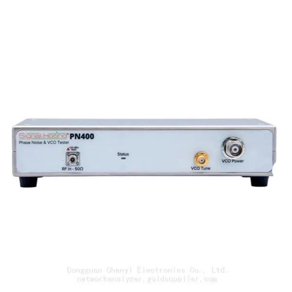
Signal Hound PN400 Phase Noise and VCO Test System 100 KHz to 43.5 GHzNegotiableMOQ: 1 Unit
-
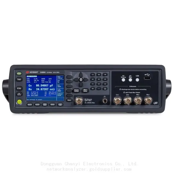
Keysight E4980A Precision LCR Meter 20 Hz to 2 MHzNegotiableMOQ: 1 Unit
-
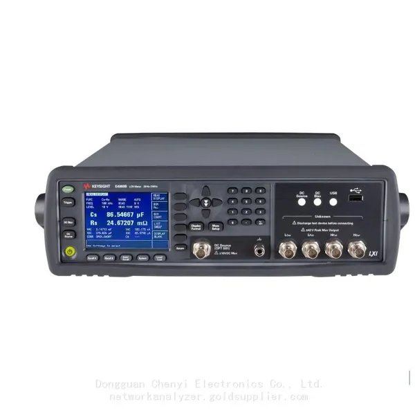
Keysight E4980B and E4980BL Precision LCR Meter 20 Hz to 2 MHzNegotiableMOQ: 1 Unit
-
Keysight U1733C Handheld LCR Meter 100Hz 120Hz 1kHz 10kHz 100kHzNegotiableMOQ: 1 Unit