
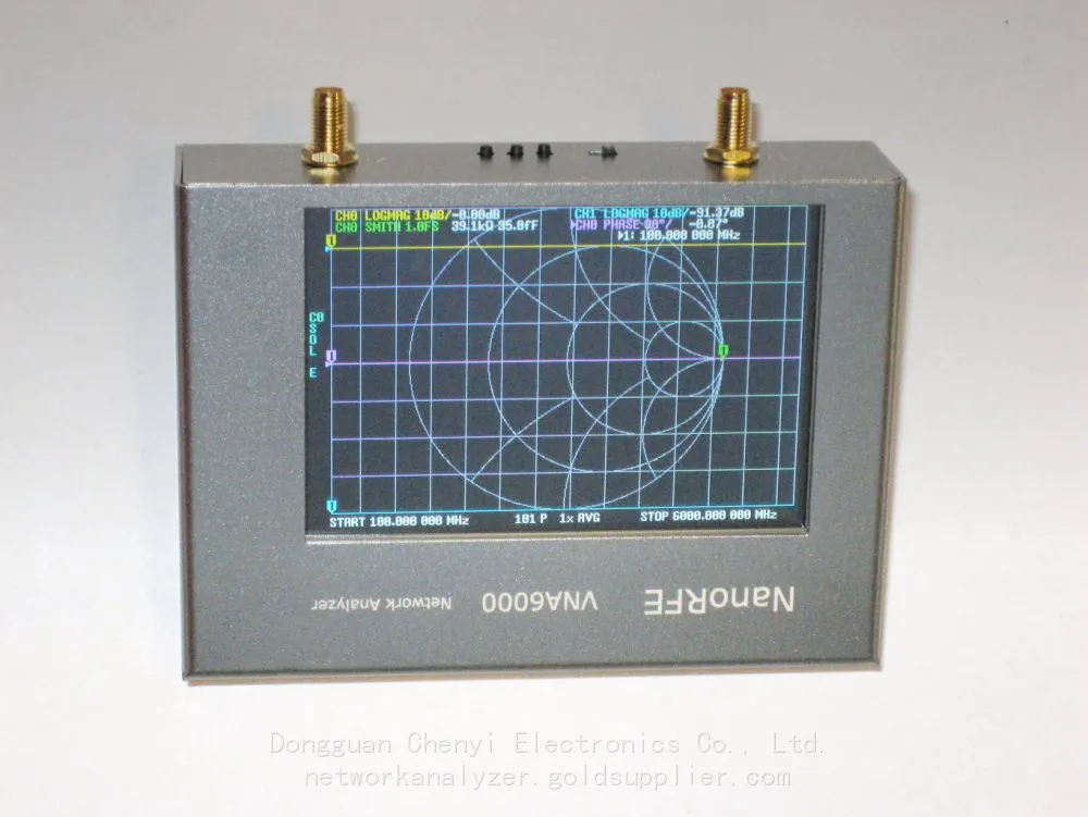
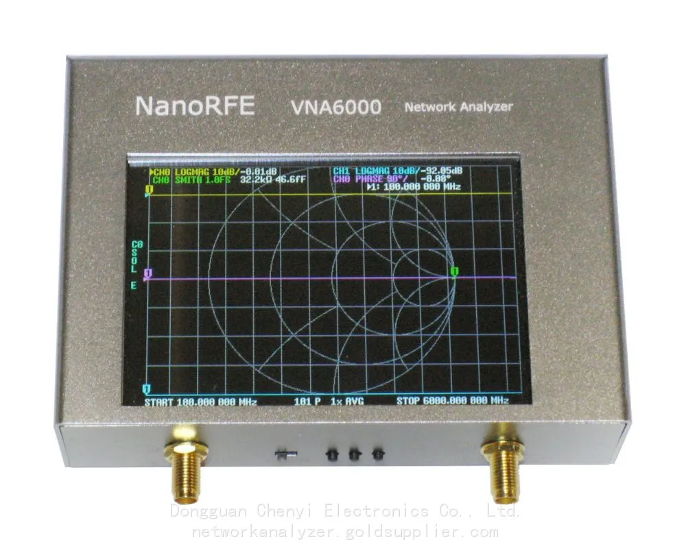
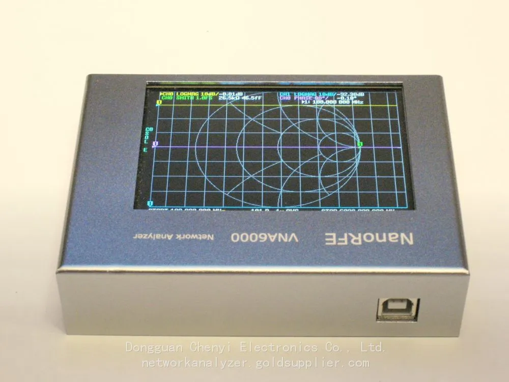
NanoRFE VNA6000-A Portable Vector Network Analyzer
The NanoRFE VNA6000-A (commonly known as NanoVNA V3) is a lightweight (approximately 300g), wideband (50kHz–6GHz), dual-port portable vector network analyzer, primarily designed for on-site testing, antenna tuning, and rapid verification of RF components.
1. Reflection analysis (S11/S22)
Return Loss: It is used to judge the quality of port matching (the higher, the better)
Standing Wave Ratio (VSWR/SWR): the most commonly used indicator for antennas/feeders (<1.5 is excellent, <2.0 is usable)
Impedance (Z): Real part R, imaginary part X, Smith chart
Applications: antenna matching, cable fault location, reflection characteristics of filters/power splitters/couplers
2. Transmission analysis (S21/S12)
Insertion Loss: Device/Cable Attenuation (Lower is Better)
Gain/Atten: Amplifier, attenuator, in-band flatness of filter
Phase / Group Delay: Phase linearity, delay fluctuation (critical for digital / broadband signals)
Applications: Filter bandwidth/rejection, amplifier gain flatness, cable phase consistency
3. Common analysis scenarios (typical usage)
Antenna measurement
Comparison of resonant frequency, bandwidth, VSWR, and gain
Quickly scan frequencies on site to find the optimal operating point
RF cable/connector testing
Loss, standing wave, breakpoint/damage localization (time domain/frequency domain)
Filter / Diplexer
Passband loss, stopband suppression, in-band ripple, insertion loss fluctuation
Amplifier / Active module
Small signal gain, bandwidth, input/output matching
PCB / RF board
Transmission line impedance, via/connector impact, matching network debugging
II. Common Issues and Fault Analysis (Medium and High Frequency Issues in Use)
1. Inaccurate measurement, data jitter, and high noise (the most common)
Phenomenon:
Curve jitter, inconsistent repeated measurements, and abnormally high standing wave/loss
The error is more pronounced in the high-frequency band (>3GHz)
Cause and solution:
Connector/cable issues (accounting for 80%+)
SMA loosening, oxidation, needle deflection, and dirt → Use a torque wrench (0.5–0.8N·m), absolute ethyl alcohol + a lint-free cloth for cleaning
Inferior/aging/bent cables → Replace with high-quality stable phase RF cables (SMA 50Ω)
Uncalibrated or calibration failure
SOLT calibration (Short/Open/Load/Thru) must be performed
Temperature change > 5℃, recalibration is required after insertion and removal
The parameter settings are unreasonable
If the Intermediate Frequency (IF) bandwidth (IFBW) is too large, adjust it to 100Hz–1kHz to improve accuracy (by slowing down)
The power is too high/low, and the points are too few → appropriately reduce the power and increase the points
Electromagnetic interference (EMI)
Keep close to WiFi/Bluetooth/frequency converter → Stay away from interference, use aluminum shielding, and ground it
2. Booting / Connection / Software Issues
Phenomenon:
The computer does not recognize the device, the software cannot connect, the screen shows no display/blurred screen, or the computer freezes
Investigation:
USB cable / unstable power supply → replace with a short and thick USB3.0 cable, and use independent power supply (avoid hub)
Driver/software version mismatch → Use the original micro-lab software, restart and reconnect
System stuck → Long press power button to reset, restore factory settings, and clear cache
3. Phase instability and large drift
Phenomenon:
Phase curve fluctuates and varies significantly with temperature/time
Reason:
Temperature drift (a common problem with portable devices)
Local oscillator not phase-locked, insufficient warm-up → Power on and allow 10–15 minutes for warm-up before testing
Large temperature difference in the environment → Try to maintain a constant temperature and avoid exposure to drafts/sunlight
4. No signal on the port / unable to detect
The port protection tube is not pulled out, and the internal relay is damaged
Calibration piece damaged / used incorrectly (Open/Short/Load mixed)
Range/frequency setting error → Restore default parameters and retest
III. Typical application scenarios (advantages of VNA6000-A)
On-site antenna engineering
Quick tuning and matching of base stations/drones/Wi-Fi/vehicular antennas, and finding the optimal location
RF production line / maintenance sampling inspection
Quick screening of filters, cables, connectors, power dividers, and loads
Amateur Radio (HAM)
Shortwave/UHF/VHF antenna, feeder, antenna tuning adjustment, standing wave monitoring
Laboratory / Teaching
Impedance matching, Smith chart teaching, and RF principle verification
IoT / Wireless Product Development
2.4G/5.8G/Wi-Fi 6 / Bluetooth / ZigBee antenna and RF front-end debugging
IV. Key points for use and maintenance (to ensure stability and reliability)
Calibration is the lifeline
It must be recalibrated after each use, change of line, change of temperature, and insertion or removal
Make good use of calibration parts: protect them from moisture and falls, and calibrate them regularly
Connector protection (most prone to failure)
Do not touch the inner conductor with bare hands. Use anhydrous ethanol and lint-free paper for cleaning
Put on the protective cap when not in use and avoid frequent hot plugging
usage habits
Preheat for ≥10 minutes
Handle with care, protect against falls and shocks (internal RF sensitive components)
Operating temperature: 0–40℃, avoid condensed water
Software and data
Save Touchstone, CSV, and PNG files in a timely manner
Firmware is updated regularly (to fix drift and linearity issues)
Recently Posted
-
Cost-Benefit Analysis: Why Choose Signal Hound BB60D for RF Testing Projects
July 2, 2026Cost-Benefit Analysis: Why Choose Signal Hound BB60D for RF Testing ProjectsIn enterprise RF testing projects, laboratory scientif Read More
 -
Ultimate Buying Guide for Signal Hound BB60D Real-Time Spectrum Analyzer: Features, Uses & Benefits
July 2, 2026Ultimate Buying Guide for Signal Hound BB60D Real-Time Spectrum Analyzer: Features, Uses & BenefitsFor RF engineers, laborator Read More
 -
Common Application Scenarios & User Cases of Signal Hound BB60D Spectrum Analyzer
July 2, 2026Common Application Scenarios & User Cases of Signal Hound BB60D Spectrum AnalyzerThe Signal Hound BB60D real-time spectrum ana Read More
 -
Signal Hound BB60D for Radar Signal Analysis & Pulse Signal Testing
July 2, 2026Signal Hound BB60D for Radar Signal Analysis & Pulse Signal TestingRadar signal analysis and pulse signal testing are high-pre
Read More

Contact Us
Recommended Products
-
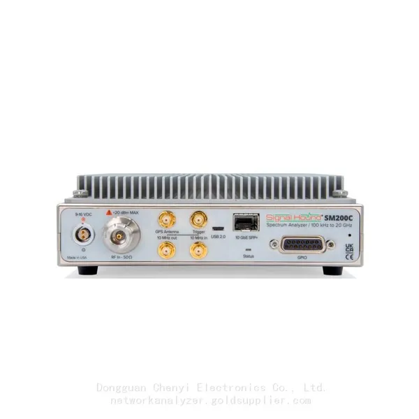
 Signal Hound SM200C 100 KHz to 20 GHz Real-time Spectrum Analyzer With 10GbE Monitoring ReceiversNegotiableMOQ: 1 Unit
 -
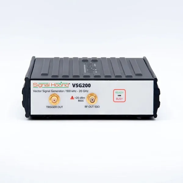
Signal Hound VSG200 Vector Signal Generator 100 KHz to 20 GHzNegotiableMOQ: 1 Unit
-
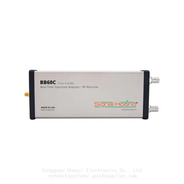
Signal Hound BB60C 9 KHz to 6 GHz Real-time Spectrum AnalyzerNegotiableMOQ: 1 Unit
-
Signal Hound BB60D 9 KHz to 6 GHz Real-time Spectrum AnalyzerNegotiableMOQ: 1 Unit
-
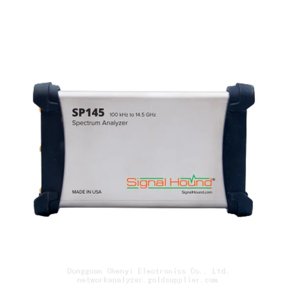
Signal Hound SP145 100 KHz to 14.5 GHz Real-time Spectrum Analyzer Monitoring ReceiversNegotiableMOQ: 1 Unit
-
Signal Hound VSG60A 50 MHz to 6 GHz GHz Vector Signal GeneratorNegotiableMOQ: 1 Unit
-
Signal Hound VSG25A 100 MHz to 2.5 GHz Vector Signal GeneratorNegotiableMOQ: 1 Unit
-
Signal Hound VNA400 40 MHz to 40 GHz 2-port Vector Network AnalyzerNegotiableMOQ: 1 Unit
-
Signal Hound PCR4200 100 KHz to 20 GHz Four-Channel Phase Coherent ReceiverNegotiableMOQ: 1 Unit
-
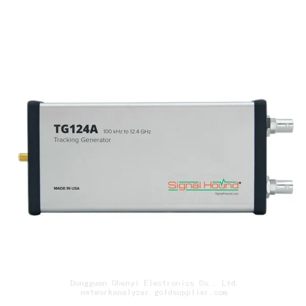
Signal Hound TG124A 100 KHz to 12.4 GHz Tracking GeneratorNegotiableMOQ: 1 Unit
-
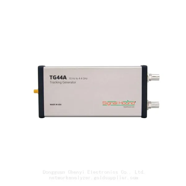
Signal Hound TG44A 10 Hz to 4.4 GHz t Tracking GeneratorNegotiableMOQ: 1 Unit
-
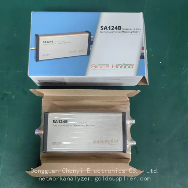
Signal Hound SA124B 100 KHz to 12.4 GHz Spectrum AnalyzerNegotiableMOQ: 1 Unit
-
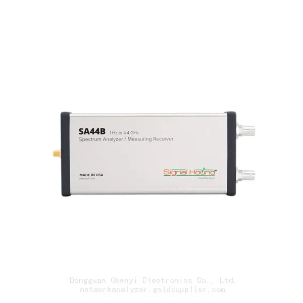
Signal Hound SA44B 1 Hz to 4.4 GHz Spectrum AnalyzerNegotiableMOQ: 1 Unit
-
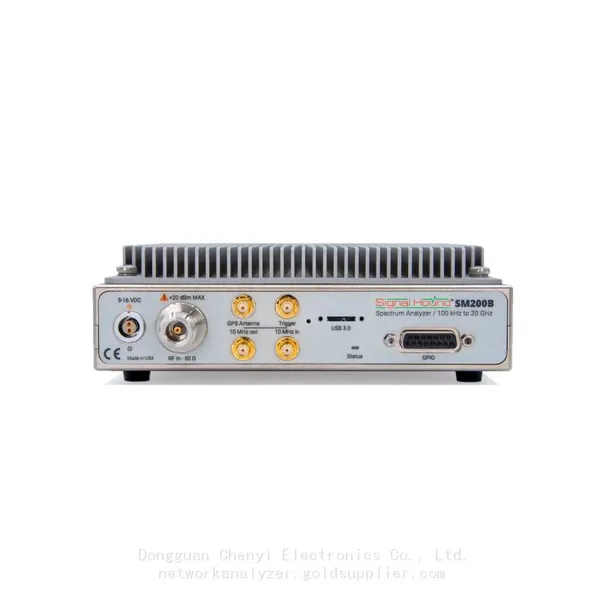
Signal Hound SM200B 100 KHz to 20 GHz Real-time Spectrum Analyzer Monitoring ReceiversNegotiableMOQ: 1 Unit
-
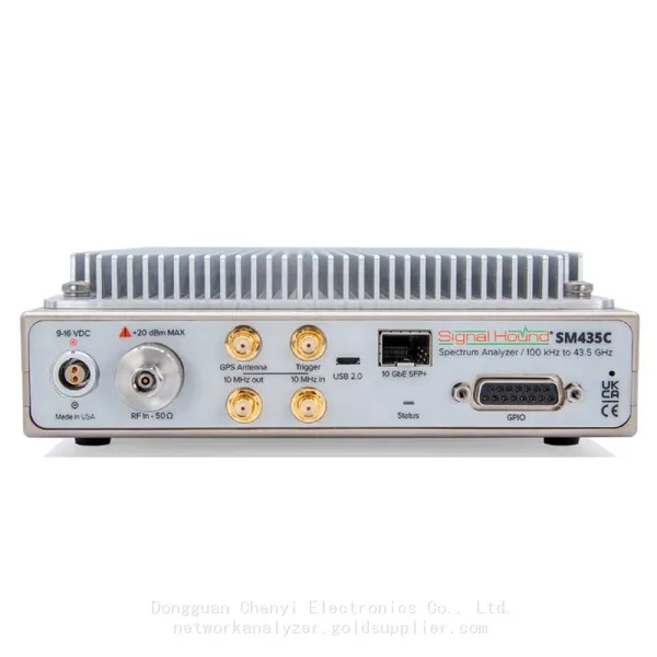
Signal Hound SM435C 100 KHz to 43.5GHz Real-time Spectrum Analyzer With 10GbE Monitoring ReceiversNegotiableMOQ: 1 Unit
-
Signal Hound SM435B 100 KHz to 43.5GHz Real-time Spectrum Analyzer Monitoring ReceiversNegotiableMOQ: 1 Unit
-
Signal Hound PN400 Phase Noise and VCO Test System 100 KHz to 43.5 GHzNegotiableMOQ: 1 Unit
-
Keysight E4980A Precision LCR Meter 20 Hz to 2 MHzNegotiableMOQ: 1 Unit
-
Keysight E4980B and E4980BL Precision LCR Meter 20 Hz to 2 MHzNegotiableMOQ: 1 Unit
-
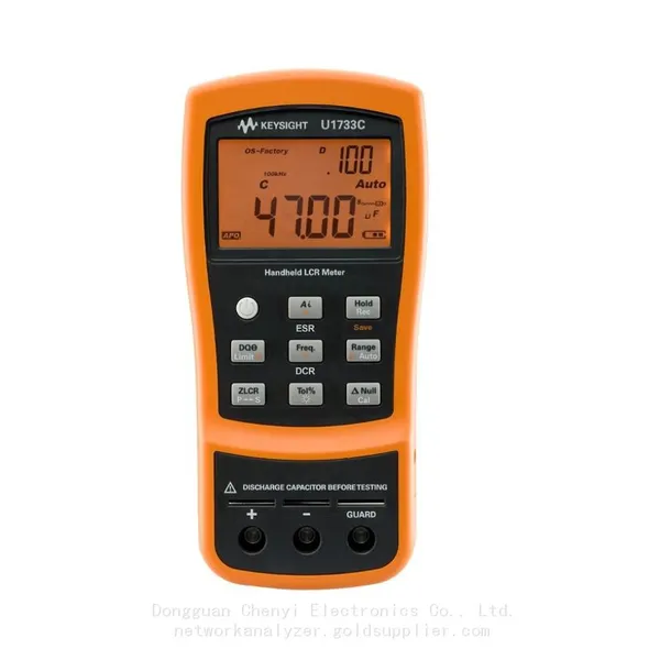
Keysight U1733C Handheld LCR Meter 100Hz 120Hz 1kHz 10kHz 100kHzNegotiableMOQ: 1 Unit