
 Business License

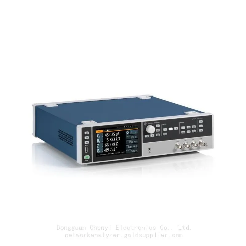
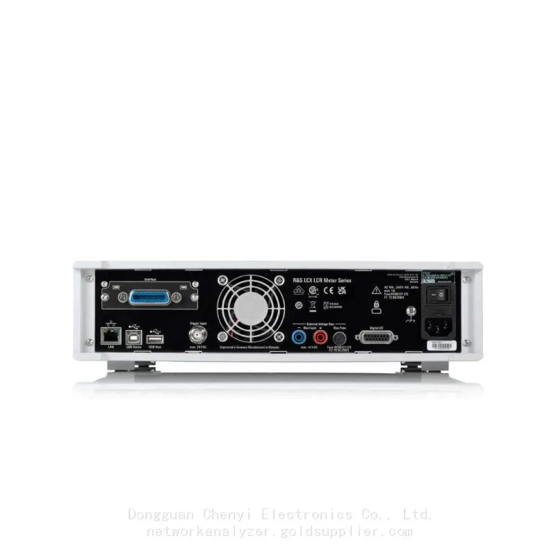
rohde schwarz LCX200 LCR mete ,DC 4 Hz to 500 kHz Upgradable 10M
rohde schwarz LCX200 LCR mete ,DC 4 Hz to 500 kHz Upgradable 10M
The top-class in component testing
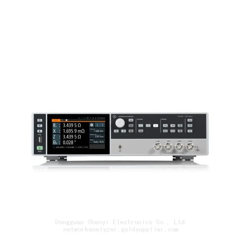
LCR meter LCX100 :DC 4 Hz to 300 kHz
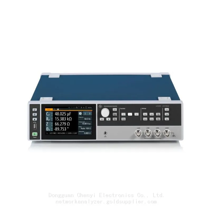
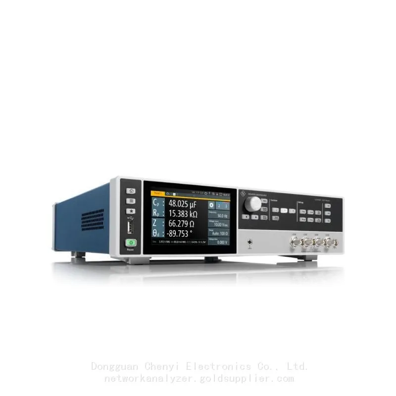
LCR meter LCX200 :DC 4 Hz to 500 kHz (Upgradable 10M)
Key facts
▶Frequency range upgradeable to 10 MHz
▶Basic accuracy of ±0.05 % for impedance measurements
▶Basic accuracy of ±0.03° for phase measurements
▶DC bias up to 40 V
▶Data logging function
The top-class in component testing
The R&S®LCX LCR meters are versatile, extremely accurate and perform measurements quickly. They are ideal for challenging applications in research, development and production. Two instrument models and various options cover applications with a test signal frequency of up to 10 MHz. Internal and external bias functions, comprehensive analysis options and versatile test fixtures expand the wide range of possible applications.
Features & benefits
Fast,accurate and versatile
Both R&S@LCX models combine high measurement speed, accuracy and versatile measurementcapabilities. This makes them ideal for standard measurements in development, for material analysis inresearch as well as for fast production testing. With their broad measurement ranges, they also coverapplications with extremely low and extremely high impedances. Three measurement times areavailable:
▶Fast:s 15 ms
▶Medium:≤ 100 ms
▶Slow:≤ 500 ms
The basic accuracy for impedance measurements is +0.05 %, and for phase measurements +0.03°
Selectable frequency range
All R&SeLCX models measure under DC conditions. The AC range already begins at 4 Hz. The upperfrequency limit on the R&SeLCX100 is 300 kHz. In its base configuration, the R&SeLCX200 is designedfor a maximum freguency of 500 kHz, this frequency limit can, however, be extended to 1 MHz or 10MHz. This means that the ideal instrument is available for any given application and budget.
Test signals for al requirements
Test signals can be generated from 100 mV to 10 V and deliver a current of up to 200 mA. Theinstruments have a selectable output impedance of 100 (2 or 10 Q. The actual current flow and thevoltage applied are measured using the monitor function.
DC bias
In many applications, an adiustable DC bias is needed to measure C and L components at diferentoperating points. The R&SeLCX100 and R&SeLCX200 generate a DC bias voltage of up to 10 V. As anoption, it is also possible to set a DC bias current (up to 200 mA). DC bias voltages of up to 40 V can beapplied at an external connection on the rear panel (R&SeLCX-K108 option) using a standard DC powersupply, for example an R&S@NGA.
Data logging function
The R&SeLCX LCR meters provide a fast logging function for recording all measured values. The datacan be saved on an external USB flash drive or transferred to an external PC via USB or LAN. With adata rate of up to 10 sample/s, the measured values are available every 100 ms.
Available models
Models:R&S®LCX100 Order number 3629.8856.02
Measurement functions:Cp, Cs, Lp, Ls, D, Q, G, Rp, Rs, Rdc, R, X, Z, Y, Θd, Θr, B, M, N
Frequency range:DC, 4 Hz to 300 kHz
Test signal voltage (RMS):10 mV to 10 V
ITest signal current:1 mA to 200 mA
Internal bias voltage:0 V - 10 V
Starting at:Price On Request
Models:R&S®LCX200 Order number 3629.8856.03
Measurement functions:Cp, Cs, Lp, Ls, D, Q, G, Rp, Rs, Rdc, R, X, Z, Y, Θd, Θr, B, M, N
Frequency range:DC, 4 Hz to 500 kHz (1 MHz or 10 MHz optional)
Test signal voltage (RMS):≤ 1 MHz: 10 mV to 10 V,≤ 5 MHz: 50 mV to 2 V,> 5 MHz: 100 mV to 1 V
ITest signal current:≤ 1 MHz: 1 mA to 100 mA,> 1 MHz to ≤ 5 MHz: 1 mA to 20 mA,> 5 MHz: 1 mA to 10 mA
Internal bias voltage:0 V - 10 V
Starting at:Price On Request
Recently Posted
-
Software-Defined Instruments: How USB Spectrum Analyzers Are Changing the RF Testing Industry
August 17, 20261. The Benchtop Instrument That Would Not Fit in a Carry-OnAn RF field engineer arrived at a remote cell site in a mountainous reg Read More
 -
Spectrum Monitoring Solutions for Broadcast Radio and Television Transmission Stations
August 17, 20261. When a 50 kW FM Transmitter Goes SilentA regional FM broadcaster serving roughly 2 million listeners lost its main transmitter Read More
 -
Understanding Spectrum Analyzer Key Specifications: DANL, Phase Noise, TOI, and RBW
August 14, 20261. The Specification That Cost Two Weeks of DebuggingAn RF design team spent two weeks trying to measure the third harmonic of a 2 Read More
 -
Real-Time Spectrum Analyzer vs Traditional Swept Spectrum Analyzer: Which One Fits Modern RF Testing
August 13, 20261. The Purchase Decision That Engineers Keep Getting WrongA test equipment manager at a contract manufacturer ordered three tradit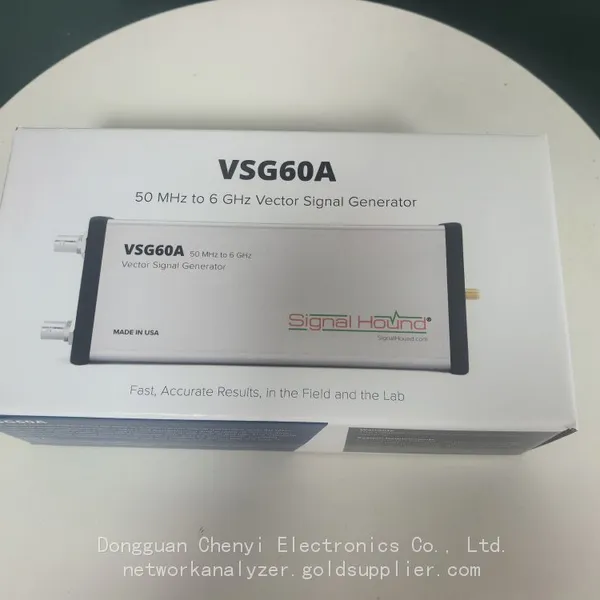 Read More

Contact Us
Recommended Products
-
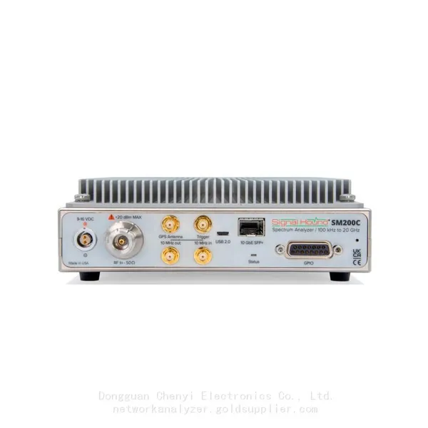
 Signal Hound SM200C 100 KHz to 20 GHz Real-time Spectrum Analyzer With 10GbE Monitoring ReceiversNegotiableMOQ: 1 Unit
 -
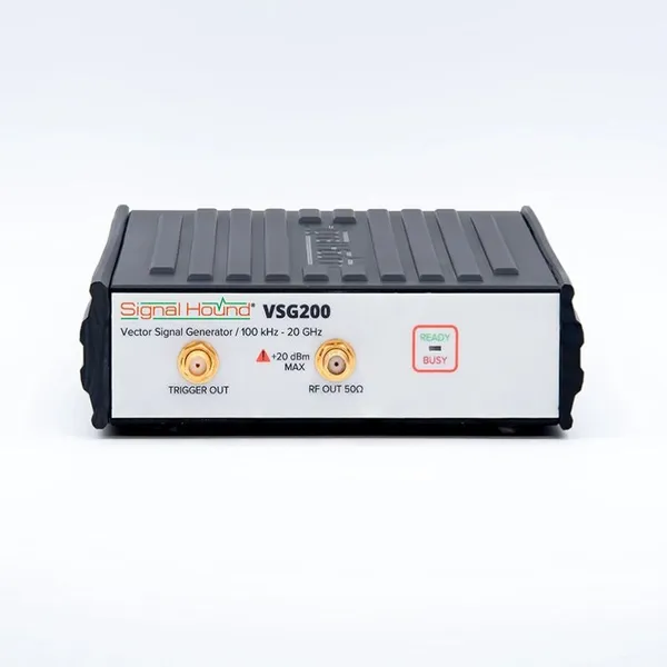
Signal Hound VSG200 Vector Signal Generator 100 KHz to 20 GHzNegotiableMOQ: 1 Unit
-
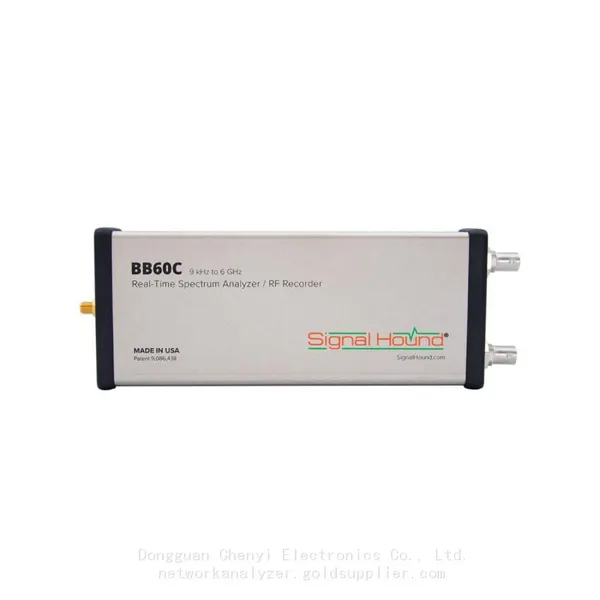
Signal Hound BB60C 9 KHz to 6 GHz Real-time Spectrum AnalyzerNegotiableMOQ: 1 Unit
-
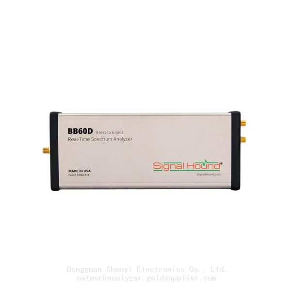
Signal Hound BB60D 9 KHz to 6 GHz Real-time Spectrum AnalyzerNegotiableMOQ: 1 Unit
-
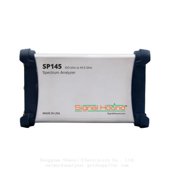
Signal Hound SP145 100 KHz to 14.5 GHz Real-time Spectrum Analyzer Monitoring ReceiversNegotiableMOQ: 1 Unit
-
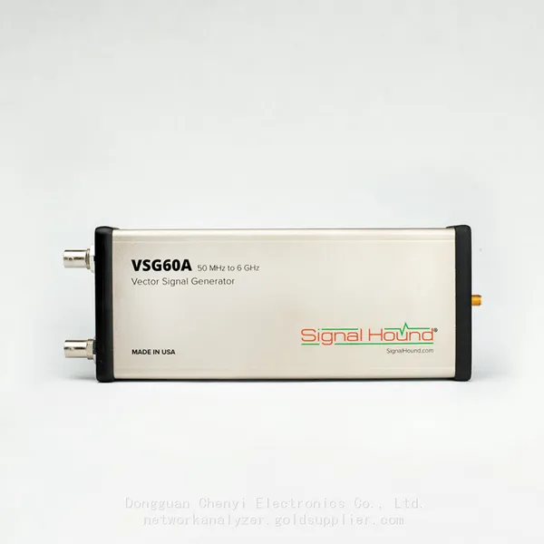
Signal Hound VSG60A 50 MHz to 6 GHz GHz Vector Signal GeneratorNegotiableMOQ: 1 Unit
-
Signal Hound VSG25A 100 MHz to 2.5 GHz Vector Signal GeneratorNegotiableMOQ: 1 Unit
-
Signal Hound VNA400 40 MHz to 40 GHz 2-port Vector Network AnalyzerNegotiableMOQ: 1 Unit
-
Signal Hound PCR4200 100 KHz to 20 GHz Four-Channel Phase Coherent ReceiverNegotiableMOQ: 1 Unit
-
Signal Hound TG124A 100 KHz to 12.4 GHz Tracking GeneratorNegotiableMOQ: 1 Unit
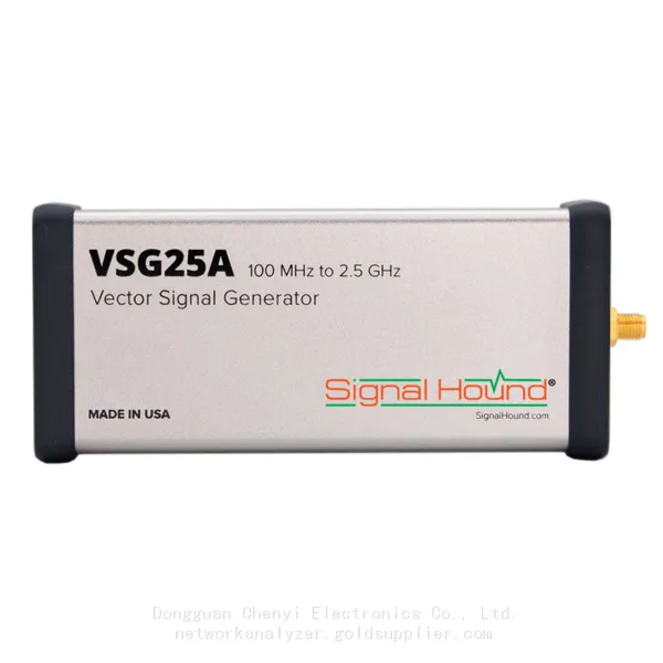
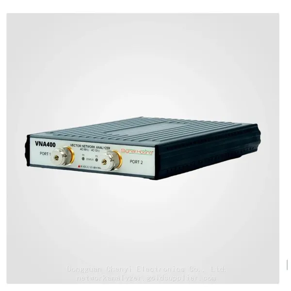
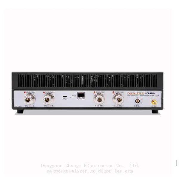
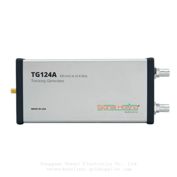
-
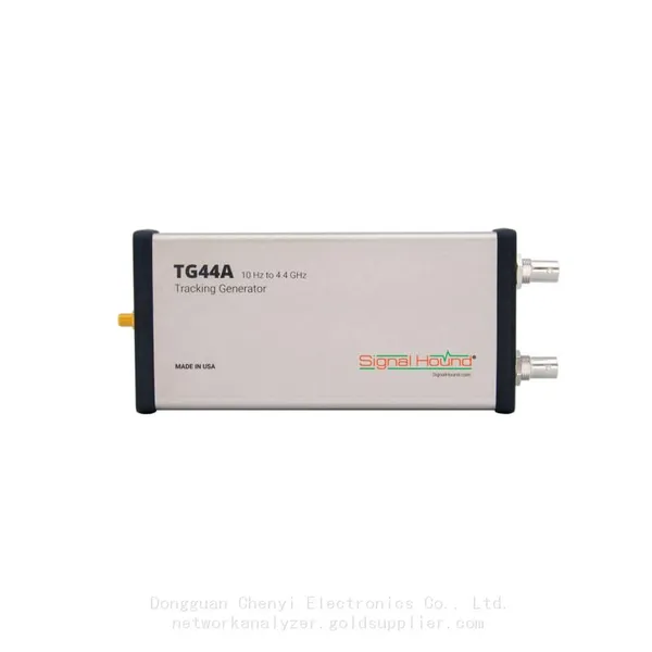
Signal Hound TG44A 10 Hz to 4.4 GHz t Tracking GeneratorNegotiableMOQ: 1 Unit
-
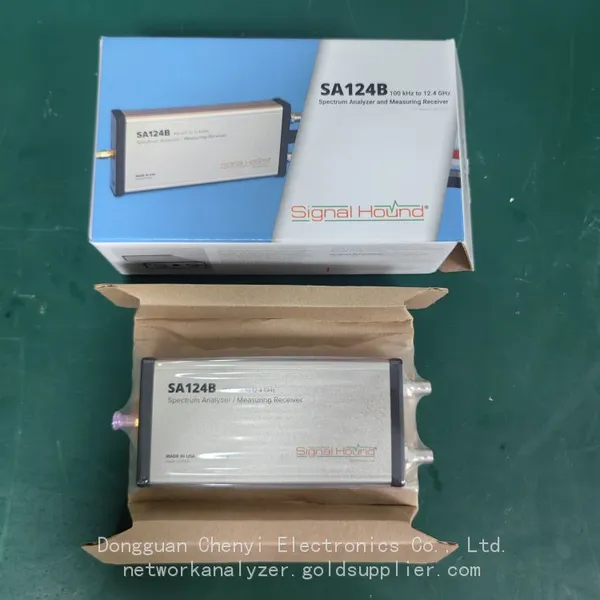
Signal Hound SA124B 100 KHz to 12.4 GHz Spectrum AnalyzerNegotiableMOQ: 1 Unit
-
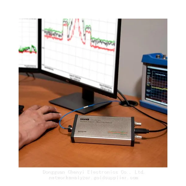
Signal Hound SA44B 1 Hz to 4.4 GHz Spectrum AnalyzerNegotiableMOQ: 1 Unit
-
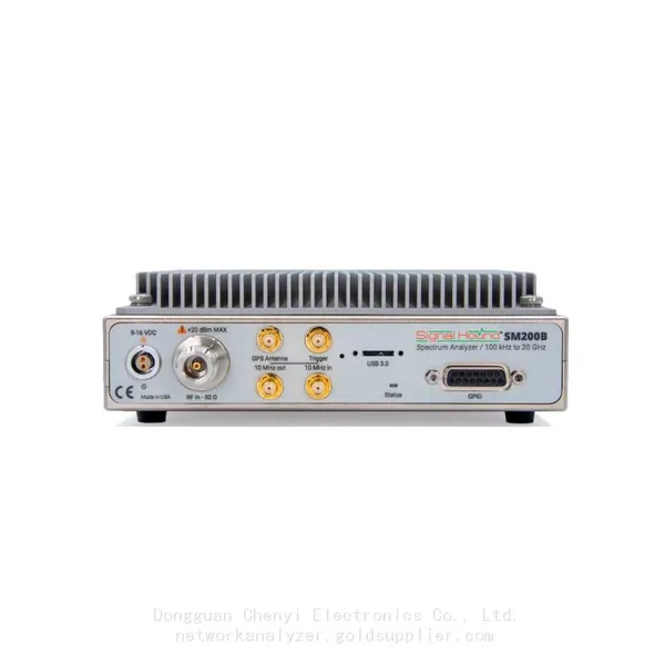
Signal Hound SM200B 100 KHz to 20 GHz Real-time Spectrum Analyzer Monitoring ReceiversNegotiableMOQ: 1 Unit
-
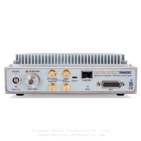
Signal Hound SM435C 100 KHz to 43.5GHz Real-time Spectrum Analyzer With 10GbE Monitoring ReceiversNegotiableMOQ: 1 Unit
-
Signal Hound SM435B 100 KHz to 43.5GHz Real-time Spectrum Analyzer Monitoring ReceiversNegotiableMOQ: 1 Unit
-
Signal Hound PN400 Phase Noise and VCO Test System 100 KHz to 43.5 GHzNegotiableMOQ: 1 Unit
-
Keysight E4980A Precision LCR Meter 20 Hz to 2 MHzNegotiableMOQ: 1 Unit
-
Keysight E4980B and E4980BL Precision LCR Meter 20 Hz to 2 MHzNegotiableMOQ: 1 Unit
-
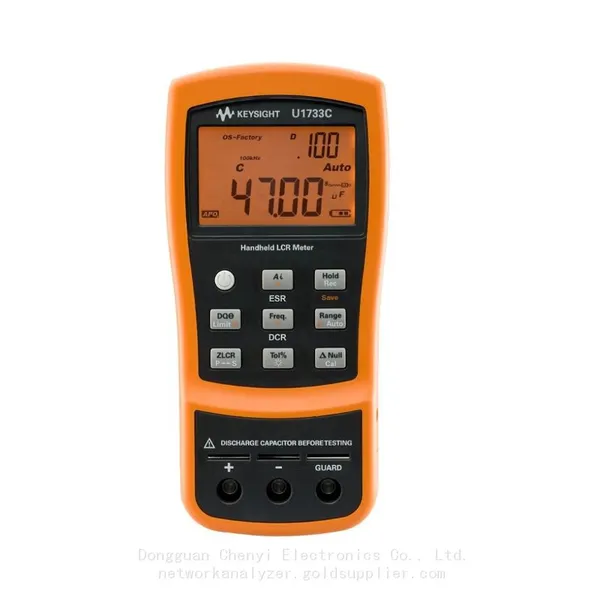
Keysight U1733C Handheld LCR Meter 100Hz 120Hz 1kHz 10kHz 100kHzNegotiableMOQ: 1 Unit